Notes:

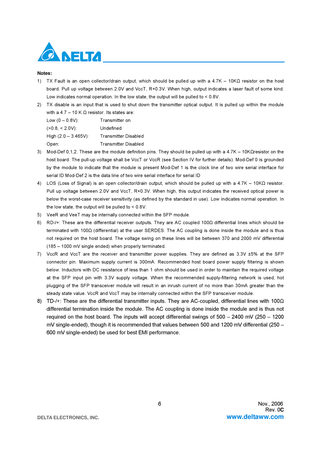
1)TX Fault is an open collector/drain output, which should be pulled up with a 4.7K – 10KΩ resistor on the host board. Pull up voltage between 2.0V and VccT, R+0.3V. When high, output indicates a laser fault of some kind. Low indicates normal operation. In the low state, the output will be pulled to < 0.8V.

2)TX disable is an input that is used to shut down the transmitter optical output. It is pulled up within the module with a 4.7 – 10 K Ω resistor. Its states are:

Low (0 – 0.8V):

Transmitter on

(>0.8, < 2.0V):

Undefined

High (2.0 – 3.465V):

Transmitter Disabled

Open:

Transmitter Disabled

3)Mod-Def 0,1,2. These are the module definition pins. They should be pulled up with a 4.7K – 10KΩresistor on the host board. The pull-up voltage shall be VccT or VccR (see Section IV for further details). Mod-Def 0 is grounded by the module to indicate that the module is present Mod-Def 1 is the clock line of two wire serial interface for serial ID Mod-Def 2 is the data line of two wire serial interface for serial ID

4)LOS (Loss of Signal) is an open collector/drain output, which should be pulled up with a 4.7K – 10KΩ resistor. Pull up voltage between 2.0V and VccT, R+0.3V. When high, this output indicates the received optical power is below the worst-case receiver sensitivity (as defined by the standard in use). Low indicates normal operation. In the low state, the output will be pulled to < 0.8V.

5)VeeR and VeeT may be internally connected within the SFP module.

6)RD-/+: These are the differential receiver outputs. They are AC coupled 100Ω differential lines which should be terminated with 100Ω (differential) at the user SERDES. The AC coupling is done inside the module and is thus not required on the host board. The voltage swing on these lines will be between 370 and 2000 mV differential (185 – 1000 mV single ended) when properly terminated.

7)VccR and VccT are the receiver and transmitter power supplies. They are defined as 3.3V ±5% at the SFP connector pin. Maximum supply current is 300mA. Recommended host board power supply filtering is shown below. Inductors with DC resistance of less than 1 ohm should be used in order to maintain the required voltage at the SFP input pin with 3.3V supply voltage. When the recommended supply-filtering network is used, hot plugging of the SFP transceiver module will result in an inrush current of no more than 30mA greater than the steady state value. VccR and VccT may be internally connected within the SFP transceiver module.

8)TD-/+: These are the differential transmitter inputs. They are AC-coupled, differential lines with 100Ω differential termination inside the module. The AC coupling is done inside the module and is thus not required on the host board. The inputs will accept differential swings of 500 – 2400 mV (250 – 1200 mV single-ended), though it is recommended that values between 500 and 1200 mV differential (250 – 600 mV single-ended) be used for best EMI performance.

6

Nov., 2006


Rev. 0C

DELTA ELECTRONICS, INC.

www.deltaww.com

Page 6
Image 6
Delta Electronics LCP-1250A4FSRH, LCP-1250A4FSRT specifications Open

LCP-1250A4FSRT, LCP-1250A4FSRH, LCP-1250A4FSR specifications

Delta Electronics has established itself as a leader in the power supply industry, and its LCP-1250A4FSRH, LCP-1250A4FSR, and LCP-1250A4FSRT models showcase cutting-edge technology and reliability for various applications. These power supplies are designed to meet the demanding requirements of contemporary electronic systems, especially in data centers, telecommunications, and industrial applications.

One of the most prominent features of these models is their high efficiency. With efficiencies typically above 94%, users can benefit from reduced energy costs and minimized heat generation, which is paramount in high-density environments. This efficiency also contributes to lower carbon footprints, aligning with global sustainability goals.

The LCP series is equipped with advanced power management capabilities, allowing for effective load sharing and redundant operation. This is particularly important in mission-critical applications where reliability cannot be compromised. The units support N+1 redundancy, ensuring that even if one unit fails, the remaining units can take over seamlessly without disrupting the system.

In terms of design, these power supplies feature a modular approach, which allows for easy scalability. Users can configure their systems according to their specific power requirements by adding or removing modules as needed. This modularity, coupled with hot-swappable capabilities, enables quick maintenance and upgrades without downtime, enhancing overall system resilience.

The LCP-1250A4FSRH, LCP-1250A4FSR, and LCP-1250A4FSRT models come equipped with sophisticated monitoring and control technologies. Users can track performance metrics through various interfaces, ensuring that the power supply operates optimally under different loads. The power supplies also feature built-in protection mechanisms against overcurrent, overvoltage, and thermal events, safeguarding both the equipment and the power supply itself.

Another significant characteristic is their compact design, which allows integration into space-constrained environments. The units are engineered to maximize airflow, thereby minimizing thermal build-up and enhancing performance stability.

In summary, Delta Electronics' LCP-1250A4FSRH, LCP-1250A4FSR, and LCP-1250A4FSRT are exemplary power supply solutions that combine efficiency, reliability, and scalability. With their advanced features and robust technologies, they are ideally suited for high-performance applications requiring consistent and dependable power delivery. These models not only meet today's demands but are also designed to adapt to the future needs of evolving electronic systems.