Digital Diagnostic Monitoring Interface
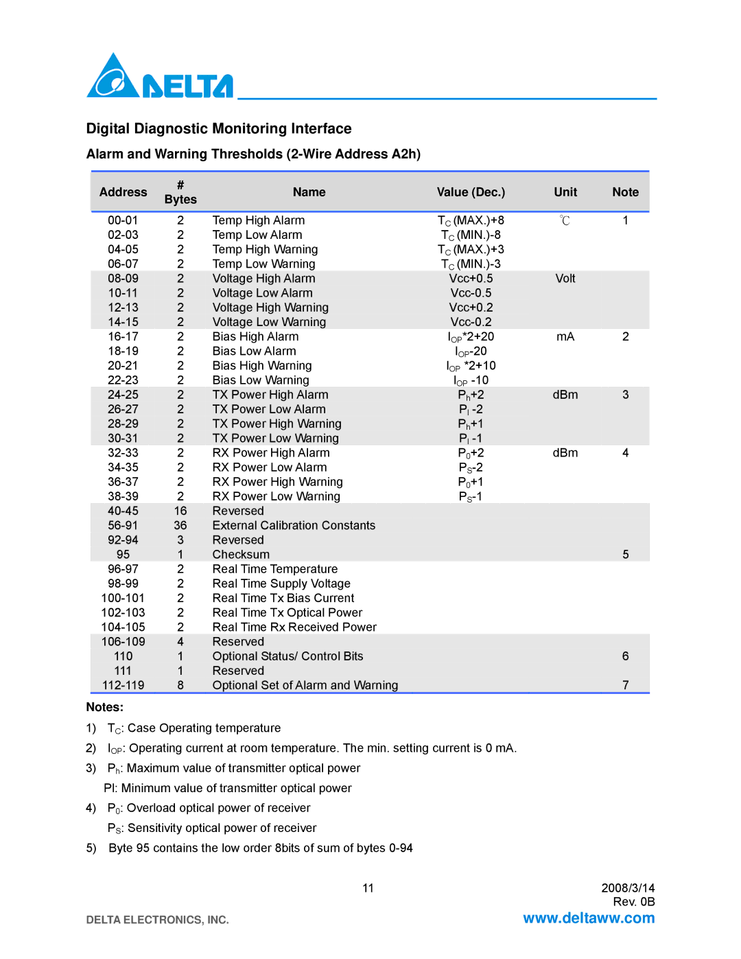
Alarm and Warning Thresholds (2-Wire Address A2h)
|
| Address |
| # |
| Name |
| Value (Dec.) |
| Unit |
|
| Note |
|
|
|
| Bytes |
|
|
|
|
|
| |||||
|
|
|
|
|
|
|
|
|
|
|
|
|
| |
|
|
|
|
|
|
|
|
|
|
|
|
|
|
|
| 2 |
| Temp High Alarm | TC (MAX.)+8 | ℃ | 1 |
| |||||||
2 |
| Temp Low Alarm | TC |
|
|
|
|
| ||||||
2 |
| Temp High Warning | TC (MAX.)+3 |
|
|
|
|
| ||||||
2 |
| Temp Low Warning | TC |
|
|
|
|
| ||||||
2 |
| Voltage High Alarm | Vcc+0.5 | Volt |
|
|
|
| ||||||
| 2 |
| Voltage Low Alarm |
|
|
|
|
| ||||||
|
| 2 |
| Voltage High Warning | Vcc+0.2 |
|
|
|
|
| ||||
|
| 2 |
| Voltage Low Warning |
|
|
|
|
|
| ||||
2 |
| Bias High Alarm | IOP*2+20 | mA | 2 |
| ||||||||
2 | Bias Low Alarm |
|
|
|
|
| ||||||||
2 |
| Bias High Warning | IOP *2+10 |
|
|
|
|
| ||||||
2 |
| Bias Low Warning | IOP |
|
|
|
|
| ||||||
2 |
| TX Power High Alarm | Ph+2 | dBm |
|
| 3 |
| ||||||
| 2 |
| TX Power Low Alarm | Pl |
|
|
|
|
| |||||
|
| 2 |
| TX Power High Warning | Ph+1 |
|
|
|
|
| ||||
|
| 2 |
| TX Power Low Warning |
| Pl |
|
|
|
|
| |||
2 |
| RX Power High Alarm | P0+2 | dBm | 4 |
| ||||||||
2 |
| RX Power Low Alarm |
|
|
|
|
| |||||||
2 |
| RX Power High Warning | P0+1 |
|
|
|
|
| ||||||
2 |
| RX Power Low Warning |
|
|
|
|
| |||||||
16 |
| Reversed |
|
|
|
|
|
|
| |||||
36 |
| External Calibration Constants |
|
|
|
|
|
|
| |||||
3 |
| Reversed |
|
|
|
|
|
|
| |||||
95 | 1 |
| Checksum |
|
|
|
|
| 5 |
| ||||
2 | Real Time Temperature |
|
|
|
|
|
|
| ||||||
2 | Real Time Supply Voltage |
|
|
|
|
|
|
| ||||||
2 | Real Time Tx Bias Current |
|
|
|
|
|
|
| ||||||
2 | Real Time Tx Optical Power |
|
|
|
|
|
|
| ||||||
2 | Real Time Rx Received Power |
|
|
|
|
|
|
| ||||||
4 |
| Reserved |
|
|
|
|
|
|
| |||||
110 | 1 |
| Optional Status/ Control Bits |
|
|
|
|
| 6 |
| ||||
111 | 1 |
| Reserved |
|
|
|
|
|
|
| ||||
8 |
| Optional Set of Alarm and Warning |
|
|
|
|
| 7 |
| |||||
Notes:
1)TC: Case Operating temperature
2)IOP: Operating current at room temperature. The min. setting current is 0 mA.
3)Ph: Maximum value of transmitter optical power
| Pl: Minimum value of transmitter optical power |
|
4) | P0: Overload optical power of receiver |
|
| PS: Sensitivity optical power of receiver |
|
5) | Byte 95 contains the low order 8bits of sum of bytes |
|
| 11 | 2008/3/14 |
|
| Rev. 0B |
DELTA ELECTRONICS, INC. | www.deltaww.com | |