MODELS SPC-15R,HD15A, N15A, AND TT15A
10,000-15,000BTU SPC-30R,HD30, AND TT30
10,000-30,000BTU
Save this manual for future reference
GENERAL HAZARD WARNING
WARNING Not for home or recreational vehicle use
SAFETY INFORMATION
ASPHYXIATION HAZARD
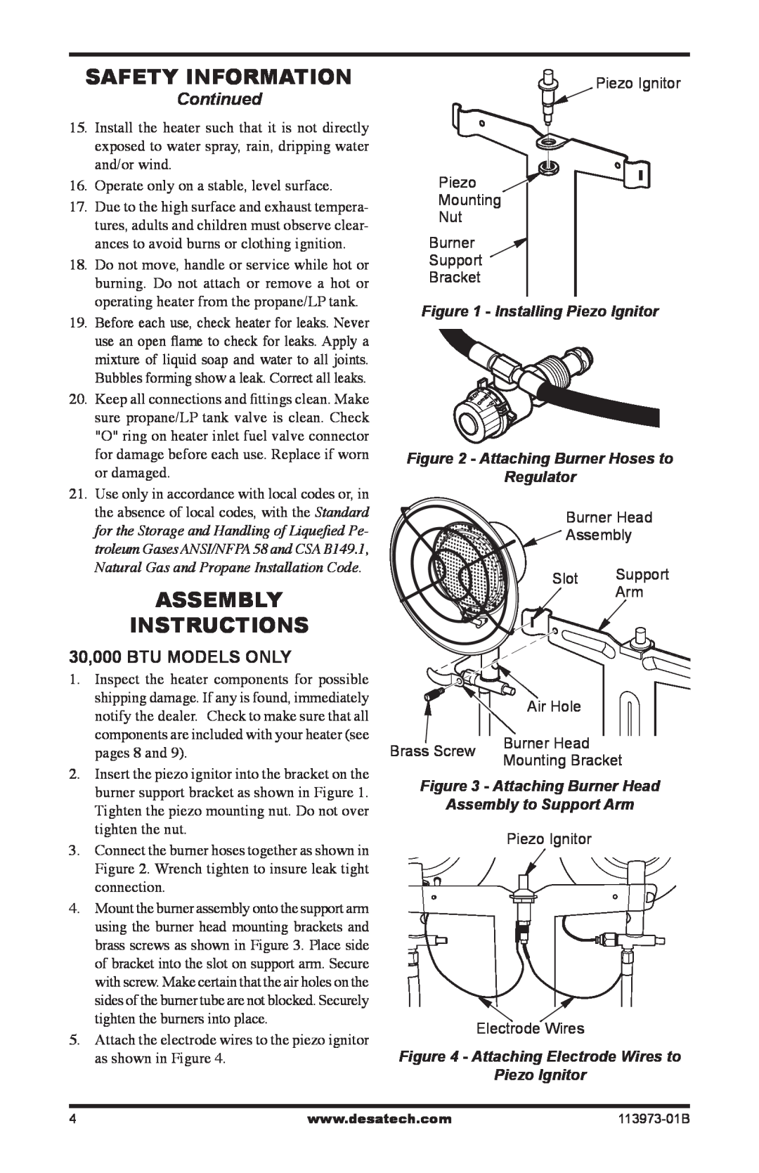
SAFETY INFORMATION
ASSEMBLY INSTRUCTIONS
Figure 1 - Installing Piezo Ignitor
Assembly to Support Arm
OPERATING INSTRUCTIONS
MAINTENANCE AND STORAGE
OPERATING INSTRUCTIONS
Continued
TO STOP HEATER
TECHNICAL SERVICE
REPLACEMENT PARTS
PARTS UNDER WARRANTY
PARTS NOT UNDER WARRANTY
ILLUSTRATED PARTS BREAKDOWN
MODELS SPC-30R,HD30, TT30
1 2 1 2 3 4 6
113973-01B
PARTS LIST
MODELS SPC-15R,HD15A, N15A, TT15A
WARRANTY AND REPAIR SERVICE
KEEP THIS WARRANTY
Limited Warranty
Propane/LP Infra-RedTank Top Heater
ADVERTENCIA
MODELOS SPC-15R,HD15A, N15A, Y TT15A
10.000-15.000BTU SPC-30R,HD30 Y TT30
10.000-30.000BTU
ADVERTENCIA GENERAL DE PELIGRO
INFORMACIÓN DE SEGURIDAD
PELIGRO DE ASFIXIA
INSTRUCCIONES DE ENSAMBLAJE
Continuación
SÓLO PARA MODELOS DE 30.000 BTU
Figura 1. Instalación del encendedor
PRECAUCIÓN No lo enci- enda desde el orificio
INSTRUCCIONES DE FUNCIONAMIENTO
PARA ENCENDER EL CALENTADOR
INSTRUCCIONES DE FUNCIONAMIENTO
MANTENIMIENTO Y ALMACENAMIENTO
Continuación
PARA APAGAR EL CALENTADOR
REPARACIONES
SERVICIO TÉCNICO
PIEZAS DE REPUESTO
PIEZAS CON GARANTÍA
CLASIFICACIÓN ILUSTRADA DE PIEZAS
MODELOS
SPC-30R,HD30, TT30
2 1 2 3 4 6 7 1514
LISTA DE PIEZAS
MODELOS SPC-15R,HD15A, N15A, TT15A
GUARDE ESTA GARANTÍA
GARANTÍA Y SERVICIO DE REPARACIÓN
Garantía limitada
1.Coupez l’arrivée de gaz de l’appareil
AVERTISSEMENT DE RISQUE GÉNÉRAL
INFORMATIONS RELATIVES
À LA SÉCURITÉ
RISQUE D’ASPHYXIE
Figure 1 - Installation de l’allumeur
ÀLA SÉCURITÉ Suite
INSTRUCTIONS D’ASSEMBLAGE
INFORMATIONS RELATIVES
ATTENTION N’allumez pas àl’orifice
NOTICE D’UTILISATION
POUR ALLUMER L’APPAREIL DE CHAUFFAGE
NOTICE D’UTILISATION
ENTRETIEN ET ENTREPOSAGE
Suite
POUR ARRÊTER L’APPAREIL DE CHAUFFAGE
SERVICE TECHNIQUE
RÉPARATION
PIÈCES DE RECHANGE
PIÈCES SOUS GARANTIE
VUE DÉTAILLÉE DES PIÈCES
MODÈLES
SPC-30R,HD30, ET TT30
2 1 2 3 4
LISTE DES PIÈCES
MODÈLES SPC-15R,HD15A, N15A, TT15A
Page
113973-01B
CONSERVEZ CETTE GARANTIE
SERVICE DE GARANTIE ET DE RÉPARATION
monter sur réservoir Garantie limitée