Manuals
/
Desa
/
Household Appliance
/
Electric Heater
Desa
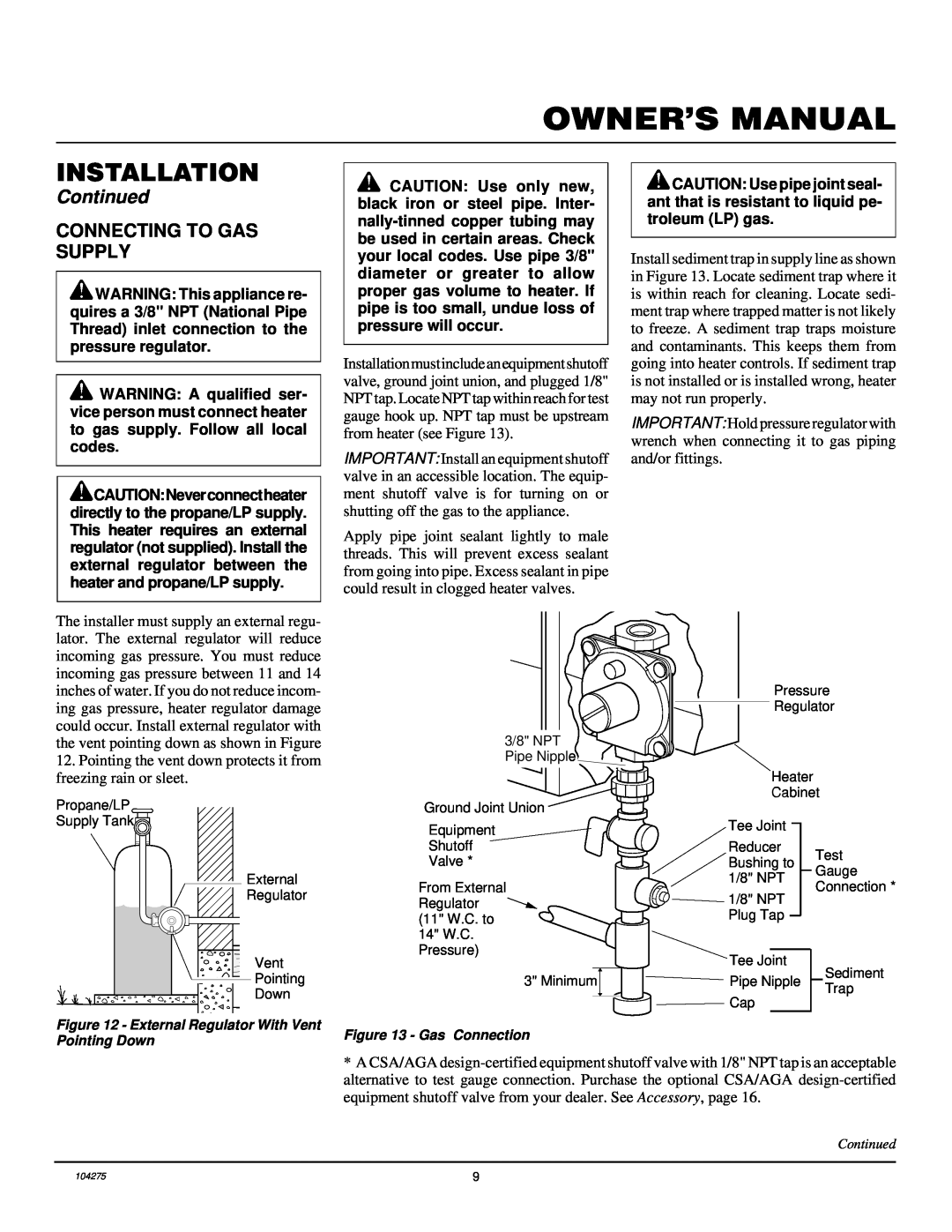
CGP10RLA Installation, Continued, Connecting To Gas Supply, Gas Connection
Models:
CGP10RLA
1
9
20
20
Download
20 pages
13.79 Kb
6
7
8
9
10
11
12
13
Troubleshooting
Specification
Install
Parts list
Connecting To Gas Supply
Warranty
Maintenance
Observedproblem
Manual Lighting Procedure
Cleaning And Maintenance
Page 9
Image 9
Page 8
Page 10
Page 9
Image 9
Page 8
Page 10
Contents
OWNER’S OPERATION AND INSTALLATION MANUAL
CGP10RLA
INFRARED VENT-FREEPROPANE/LP GAS HEATER
PROPANE/LP GAS HEATER
SAFETY INFORMATION
PRODUCT IDENTIFICATION
PRODUCT FEATURES
LOCAL CODES
UNPACKING
AIR FOR COMBUSTION AND VENTILATION
PROPANE/LP GAS HEATER
PROVIDING ADEQUATE VENTILATION
Continued
AIR FOR COMBUSTION AND VENTILATION
DETERMINING FRESH-AIRFLOW FOR HEATER LOCATION
AIR FOR COMBUSTION AND VENTILATION
PROPANE/LP GAS HEATER
Continued
Figure 2 - Ventilation Air from Inside Building
INSTALLATION ITEMS
INSTALLATION
INSTALLING HEATER TO WALL
CHECK GAS TYPE
Installing Two Mounting Screws
INSTALLATION
Installing Bottom Mounting Screw
PROPANE/LP GAS HEATER
CONNECTING TO GAS SUPPLY
INSTALLATION
Continued
Figure 13 - Gas Connection
INSTALLATION
OPERATING HEATER
FOR YOUR SAFETY READ BEFORE LIGHTING
PROPANE/LP GAS HEATER
OPERATING HEATER
MANUAL LIGHTING PROCEDURE
Continued
LIGHTING INSTRUCTIONS
INSPECTING BURNER
CLEANING AND MAINTENANCE
CLEANING BURNER PILOT AIR INLET HOLE
PROPANE/LP GAS HEATER
OBSERVED PROBLEM
TROUBLESHOOTING
POSSIBLE CAUSE
REMEDY
OBSERVEDPROBLEM
TROUBLESHOOTING
PROPANE/LP GAS HEATER
Continued
Maintenance, page
TROUBLESHOOTING
Continued
Refer to Air for Combustion and Venti
REPLACEMENT PARTS
SPECIFICATIONS
TECHNICAL SERVICE
SERVICE HINTS
PARTS CENTRALS
PROPANE/LP GAS HEATER
ILLUSTRATED PARTS BREAKDOWN
PART
PARTS LIST
NUMBER
DESCRIPTION
INTERNATIONAL
WARRANTY INFORMATION
NOT A UPC
Model
Top
Page
Image
Contents