troubleshooting
Continued
Identifying error signals from receiver
OBSERVED PROBLEM | POSSIBLE CAUSE | REMEDY |
|
|
|
Longsignals(0.8secondtone,0.2 | Battery nearly down. (When | Replace battery |
second break) during ignition | signal appears the first time ap- |
|
| proximately 10 ignitions left) |
|
5 second continuous tone | Cable is not connected, ON/OFF | Connect cables |
| switch is in OFF position |
|
5 short signals (8.2 second tone, | Ignition not successful, possible | Switch to ON. Repeat |
0.2 second break) | air in supplyline | procedure |
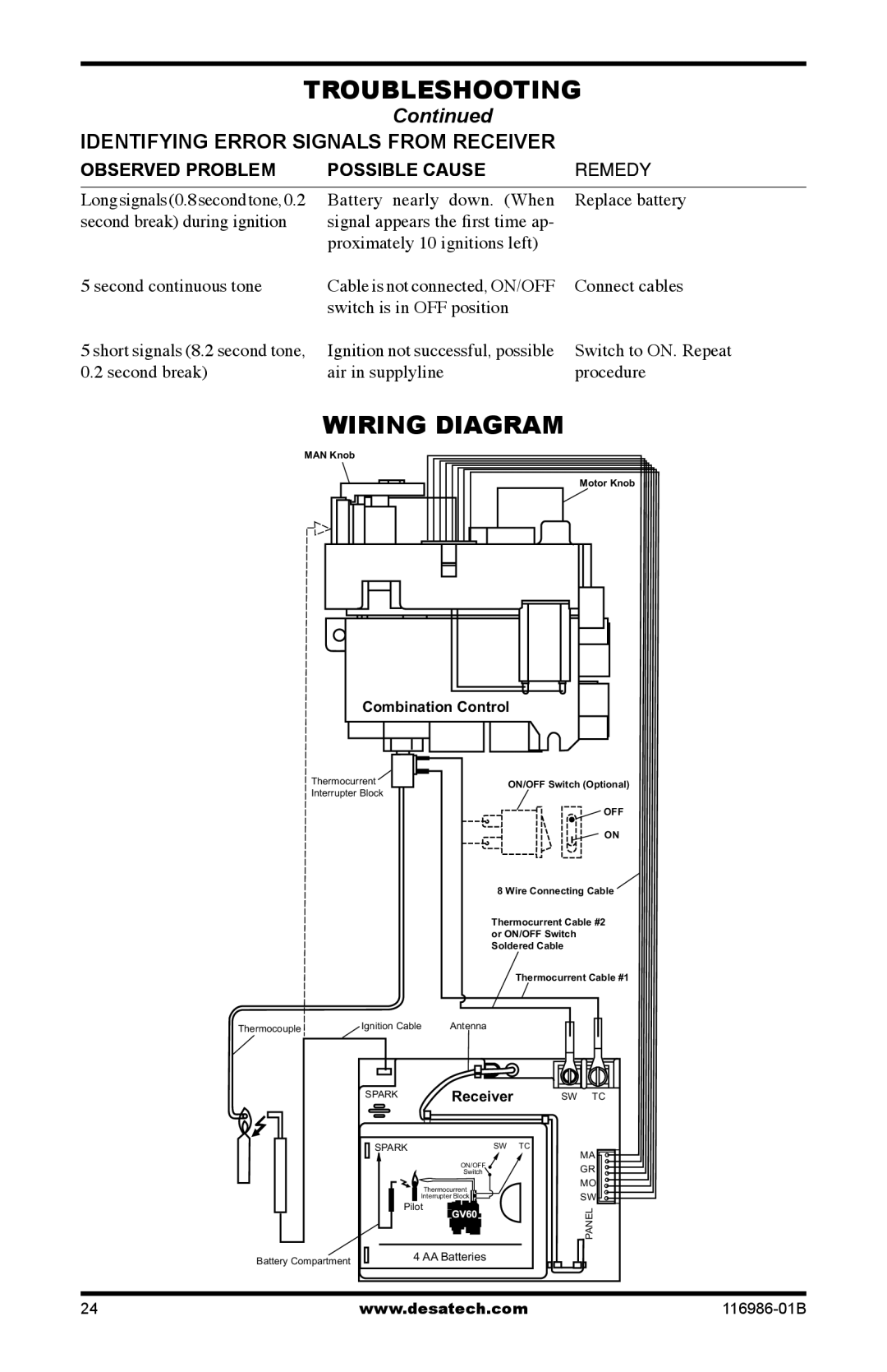
Wiring Diagram
MAN Knob
Motor Knob
Combination Control
Thermocurrent | ON/OFF Switch (Optional) | |
Interrupter Block | ||
| ||
| OFF | |
| ON | |
| 8 Wire Connecting Cable | |
| Thermocurrent Cable #2 | |
| or ON/OFF Switch | |
| Soldered Cable | |
| Thermocurrent Cable #1 |
ThermocoupleIgnition Cable Antenna
SPARK | Receiver |
SPARK | SW TC |
| ON/OFF |
| Switch |
| Thermocurrent |
| Interrupter Block |
Pilot | |
Battery Compartment | 4 AA Batteries |
| |
SW TC
MA
GR
MO
SW
PANEL
24 | www.desatech.com |