Guide Dutilisation Manual DE Instrucciones
General Safety Rules For All Tools
Electrical Safety
Work Area
Service
Additional Specific Safety Instructions for Grinders
Personal Safety
Tool USE and Care
Always Wear EYE Protection When Using this Tool
Causes and Operator Prevention of Kickback
Components Fig
Spindle Lock Button Dust Ejection System Spindle not shown
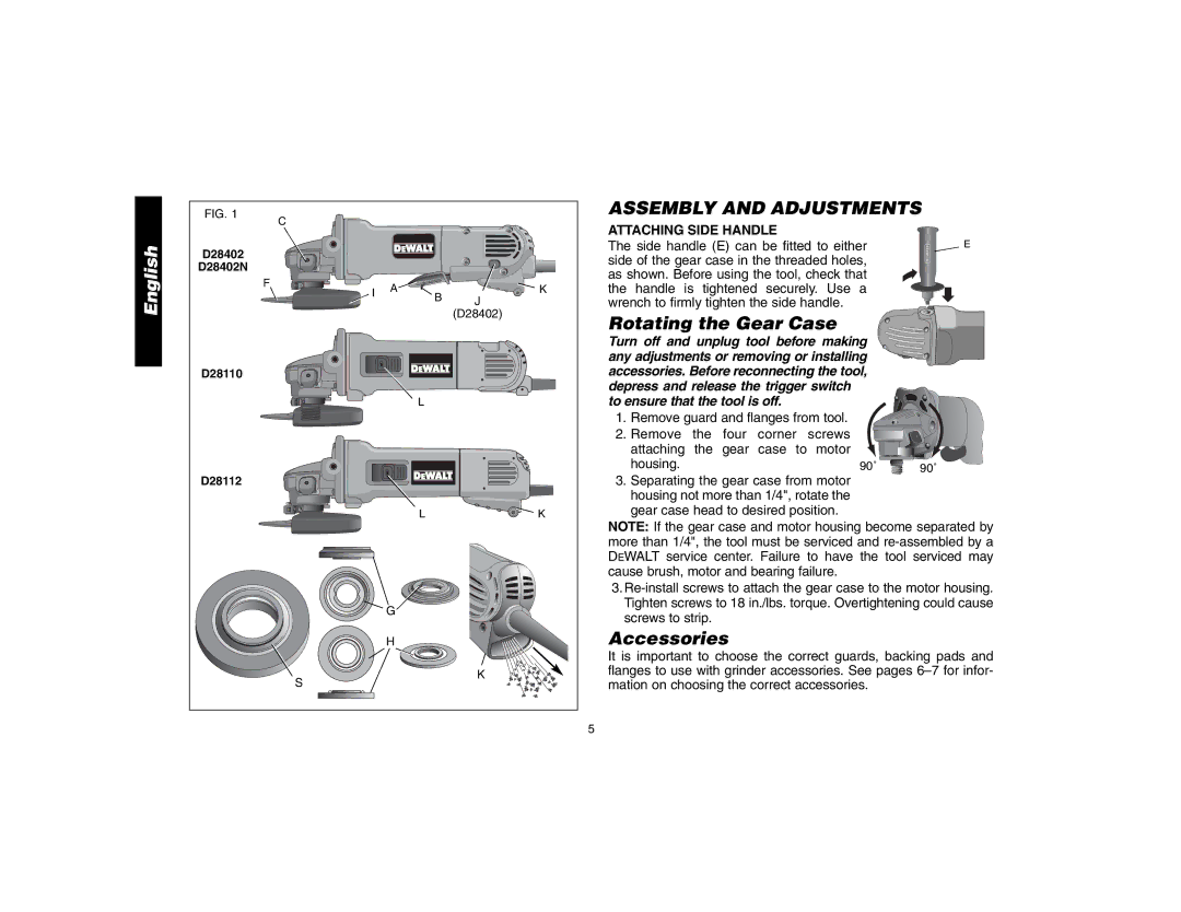
Rotating the Gear Case
Assembly and Adjustments
Accessories
Attaching Side Handle
Type 27 depressed Center wheel Threaded clamp nut
2 Grinding Wheels Wire Wheels
Mounting Guard
Mounting and Removing Guard D28112, D28402, D28402N
Sanding Discs 2 Sanding Flap Discs
Guards and Flanges
Switches
Operation
Mounting and Removing Guard
Spindle Lock
LOCK-ON Button D28402
On button J. The tool will continue to
Mounting and Removing Hubbed Wheels
Back motion to avoid creating
Must be used with included flanges. See
Surface Grinding with Grinding Wheels
Edge Grinding with Grinding Wheels
Mounting Sanding Backing Pads
Using Sanding Backing Pads
Surface Finishing with Sanding Flap Discs
Very Fine Finishing
Mounting and Using Wire Brushes and Wire Wheels
Mounting Wire CUP Brushes and Wire Wheels
Using Wire CUP Brushes and Wire Wheels
Mounting and Using Cutting Type 1 Wheels
Mounting Closed Type 1 Guard
Mounting Cutting Wheels
Accessories Three Year Limited Warranty
Maintenance
Cleaning
Lubrication
Addition to the warranty, Dewalt tools are covered by our
Year Free Service
DAY Money Back Guarantee
Aire DE Travail
Règles de sécurité Généralités
Conserver CES Directives
Mesures DE Sécurité Électricité
Sécurité Personnelle
Utilisation ET Entretien DE L’OUTIL
Directives de sécurité supplémentaires pour meuleuses
Entretien
Causes de l’effet de rebond et prévention de l’opérateur
D28402 D28402N D28110 D28112
Positionnement du carter d’engrenages
Composants fig
Assemblage ET Réglages
Fixation DE LA Poignée Latérale
Accessoires
Montage du dispositif de protection
Ouvert, tourner le dispositif I dans la
Dispositif de
Montage ET Démontage DU Dispositif DE Protection D28110
La meuleuse avec un dispositif de protection desserré
Fonctionnement
Dispositifs de protection et brides
Alignées, puis tirer sur le dispositif de protection
Bouton DE Verrouillage D28402
Interrupteurs
Interrupteur À Palette D28402 D28402N
Interrupteur Coulissant D28110, D28112
Montage DE Meules Sans Moyeu
Dispositif DE Verrouillage DE LA Broche
Montage ET Démontage DE Meules À Moyeu
Poser la bride tournante sur collet battu
Meulage DE Finition Avec DES Meules
Meulage DE Bordure Avec DES Meules
Finition DE Surface Avec DES Disques À Lamelles DE Ponçage
Utilisation DES Patins DE Ponçage ET D’APPUI
Montage DES Patins D’APPUI ET DE Ponçage
De la pièce
Métalliques ou de brosses métalliques à touret
Montage et utilisation de meules de coupe type
Montage D’UN Dispositif DE Protection Fermé Type
Montage DE Meules DE Coupe
Entretien
Nettoyage
Utilisation DES Meules DE Coupe
Garantie limitée de trois ans
Lubrification
Réparations
Contrat D’ENTRETIEN Gratuit D’UN AN
Área DE Trabajo
Instrucciones de seguridad generales
Conserve Estas Instrucciones
Seguridad Eléctrica
Seguridad Personal
Más
Calibre del cordón AWG No recomendado
USO Y Cuidados DE LA Herramienta
Servicio
Causas del retroceso y su prevención por parte del operador
D28402 D28402N D28110 D28112
Como girar la caja de engranajes
Componentes Fig
Ensamblado Y Ajustes
Accesorios
Instalación del protector
Montaje Y Remoción DEL Protector D28110
Operación
Protectores y bridas
Interruptores
Interruptor DE Paleta D28402, D28402N
Bloqueo DEL EJE
Interruptor Deslizante D28110, D28112
Botón DE Bloqueo D28402
Montaje Y Remoción DE Discos CON Cubo
Ensamblado DE Discos SIN Cubo
Esmerilado DE Superficies CON Discos Para Esmerilar
De aplicarla a la superficie de trabajo
Esmerilado DE Bordes CON Discos Para Esmerilar
Acabado DE Superficies CON Discos Para Lijar
Mienta hacia adelante y hacia atrás
Montaje y uso de cepillos de alambre y discos de alambre
USO DE Almohadillas DE Respaldo Para Lijar
Montaje y uso de los discos de corte Tipo
La sección elevada piloto
Montaje DEL Protector Cerrado Tipo
Montaje DE LOS Discos DE Corte
Piloto en dirección opuesta al disco
Lubricación
Mantenimiento
Limpieza
Reparaciones
AÑO DE Servicio Gratuito
Garantía limitada por tres años
Excepciones
Garantía DE Reembolso DE SU Dinero POR 90 Días
CULIACAN, SIN
Especificaciones D28402, D28402N