Dialogic®
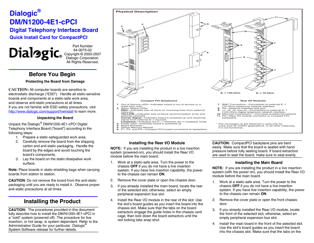
Physical Description
11 ![]()
DM/N1200-4E1-cPCI
Digital Telephony Interface Board
Quick Install Card for CompactPCI
Part Number
5 | 6 |
4 |
|
CompactPCI |
|
POWER |
|
3
![]() 6
6
E T H E R N E T
![]() 10
10![]()
![]() 9
9
E
T
H
E
R
N
E
T
![]() 7
7
Copyright ©
Dialogic Corporation.
All Rights Reserved.
Before You Begin
|
|
|
|
| T |
|
|
|
|
|
| E |
|
|
|
|
|
| S | 8 |
|
|
|
|
| T | |
|
| 1 |
|
| P | |
| A | 2 |
|
| ||
|
|
| O |
| ||
| L |
|
|
| R |
|
| A |
|
| RED | T |
|
| R |
|
|
|
| |
| M |
|
| YEL |
|
|
| S |
|
| CARR |
|
|
2 | / |
|
| SGNL |
|
|
S 3 | 4 | LOOP |
|
| ||
BACK |
|
| ||||
| T |
|
|
|
|
|
| A |
|
| RED |
|
|
| T |
|
|
|
| |
| U |
|
| YEL |
|
|
| S |
|
| CARR |
|
|
|
|
|
| SGNL |
|
|
|
|
|
| LOOP |
|
|
|
|
|
| BACK |
|
|
T
E
S
T
P
O
R
T
![]() 7
7
Protecting the Board from Damage
CAUTION: All computer boards are sensitive to electrostatic discharge (“ESD”). Handle all
and observe
If you are not familiar with ESD safety precautions, visit http://www.dialogic.com/support/hwinstall to learn more.
Unpacking the Board
Unpack the Dialogic®
1 | OUT OF |
| |
| SERVICE |
Compact PCI Baseboard
1.Out of Service
2.Alarm Status LEDs:
Carrier
3.Power
4.Board Extractor
5.Global Memory Module
6.P1, P4, and
|
|
Rear I/O Modules
7.BNC
8.
9.J1, J2, J3, and
10.Ethernet
11.
*The connection to the Ethernet is used only for
1.Prepare a
2.Carefully remove the board from the shipping carton and
3.Lay the board on the
Note: Place boards in
CAUTION: Do not remove the board from the
Installing the Product
CAUTION: The procedures provided in this document fully describe how to install the
Installing the Rear I/O Module
NOTE: If you are installing the product in a live insertion system
1.Work at a
2.Remove the cover plate or open the chassis door.
3.If you already installed the main board, locate the rear of the selected slot; otherwise, select an empty peripheral expansion bus slot.
4.Install the Rear I/O module in the rear of the slot. Use the slot’s board guides as you insert the board into the chassis slot. Make sure that the tabs on the board extractors engage the guide holes in the chassis card cage, then lock down the board extractors until the red locking tabs snap shut.
CAUTION: CompactPCI backplane pins are bent easily. Make sure that the board is seated with hand pressure before fully seating board. If board extractors are used to seat the board, make sure to seat evenly.
Installing the Main Board
NOTE: If you are installing the product in a live insertion system (with the power on), you should install the Rear I/O module before the main board.
1.Work at a
2.Remove the cover plate or open the front chassis door.
3.If you already installed the Rear I/O module, locate the front of the selected slot; otherwise, select an empty peripheral expansion bus slot.
4.Install the main board in the front of the selected slot. Use the slot’s board guides as you insert the board into the chassis slot. Make sure that the tabs on the