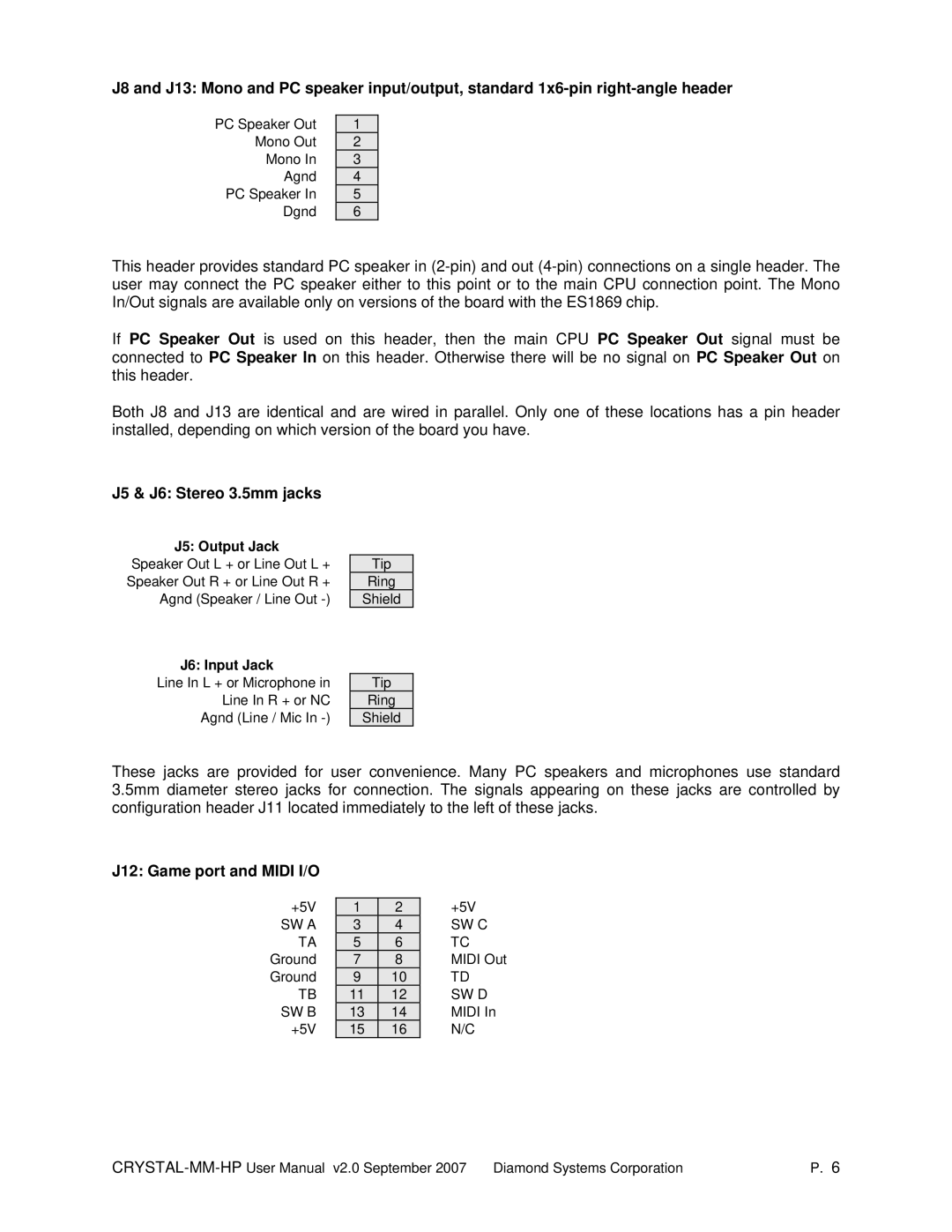
J8 and J13: Mono and PC speaker input/output, standard
PC Speaker Out
Mono Out
Mono In
Agnd
PC Speaker In
Dgnd
1 |
2 |
3 |
4 |
5 |
6 |
This header provides standard PC speaker in
If PC Speaker Out is used on this header, then the main CPU PC Speaker Out signal must be connected to PC Speaker In on this header. Otherwise there will be no signal on PC Speaker Out on this header.
Both J8 and J13 are identical and are wired in parallel. Only one of these locations has a pin header installed, depending on which version of the board you have.
J5 & J6: Stereo 3.5mm jacks
J5: Output Jack
Speaker Out L + or Line Out L + Speaker Out R + or Line Out R + Agnd (Speaker / Line Out
Tip |
Ring |
Shield |
J6: Input Jack
Line In L + or Microphone in Line In R + or NC Agnd (Line / Mic In
Tip |
Ring |
Shield |
These jacks are provided for user convenience. Many PC speakers and microphones use standard 3.5mm diameter stereo jacks for connection. The signals appearing on these jacks are controlled by configuration header J11 located immediately to the left of these jacks.
J12: Game port and MIDI I/O
+5V | 1 | 2 | +5V |
SW A | 3 | 4 | SW C |
TA | 5 | 6 | TC |
Ground | 7 | 8 | MIDI Out |
Ground | 9 | 10 | TD |
TB | 11 | 12 | SW D |
SW B | 13 | 14 | MIDI In |
+5V | 15 | 16 | N/C |
P. 6 |