Install Guide
Diagnostic LEDs
COL/TP: Collisions are occurring on the
Link: There is an active connection to
Power: Unit is receiving power
RCV/CX Unit is receiving packets from the 10BASE2 network COL/CX: Collisions are occurring on the 10BASE2 network
Configuration
Next to the COAX cable connector, there is a DIP switch that control the 50 ohm termination resistor (Figure 1). These switches support a variety of configurations. Both switches are shipped in the UP position (default). Other configurations include:
If the
•Placing switch 1: UP and
•Placing switch 2: DOWN
If the
• Place both switches (1 and 2) in the DOWN position
Note: For this configuration, you do not need a 50 ohm terminator on the COAX segment of the
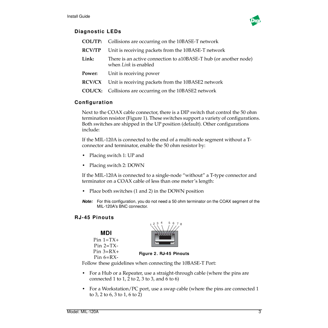
RJ - 45 Pinouts
1 2 3 4 5 6 7 8
MDI
Pin 1=TX+
Pin 2=TX-
Pin 3=RX+
Pin 6=RX-
Follow these guidelines when connecting the
•For a Hub or a Repeater, use a
•For a Workstation/PC port, use a swap cable (where the pins are connected 1 to 3, 2 to 6, 3 to 1, 6 to 2)
Model: | 3 |