2003 Dimension One Spas and @ Home Hot Tubs
Planning Guide and Installation Manual
Export D1 Hot Tubs
|
|
|
|
|
|
|
|
|
|
|
|
|
|
|
|
|
|
|
|
|
|
|
|
|
| Circuit |
|
| Wire |
|
|
| Model |
|
| Power |
|
| Circuit |
|
| Wire |
|
| Model | Power |
| Protection |
|
| Gauge |
|
|
|
|
|
|
|
|
| Protection |
|
| Gauge |
|
| Arena | 240V |
| 1x16 |
|
| #8 AWG |
|
|
| Chairman II |
|
| 240V |
|
| 1x16 |
|
| #8 AWG |
|
|
| 240V |
| 2x16 |
|
| #8 AWG |
|
|
|
|
|
| 240V |
|
| 2x16 |
|
| #8 AWG |
|
|
| 240V |
| 1x32 |
|
| #6 AWG |
|
|
|
|
|
| 240V |
|
| 1x32 |
|
| #6 AWG |
|
| Aurora II | 240V |
| 1x16 |
|
| #8 AWG |
|
|
| Diplomat |
|
| 240V |
|
| 1x16 |
|
| #8 AWG |
|
|
| 240V |
| 2x16 |
|
| #8 AWG |
|
|
|
|
|
| 240V |
|
| 2x16 |
|
| #8 AWG |
|
|
| 240V |
| 1x32 |
|
| #6 AWG |
|
|
|
|
|
| 240V |
|
| 1x32 |
|
| #6 AWG |
|
| Aurora HP | 240V |
| 1x16 |
|
| #8 AWG |
|
|
| Nautilus |
|
| 240V |
|
| 1x16 |
|
| #8 AWG |
|
|
| 240V |
| 2x16 |
|
| #8 AWG |
|
|
|
|
|
| 240V |
|
| 2x16 |
|
| #8 AWG |
|
|
| 240V |
| 1x32 |
|
| #6 AWG |
|
|
|
|
|
| 240V |
|
| 1x32 |
|
| #6 AWG |
|
| Caliente | 240V |
| 1x16 |
|
| #8 AWG |
|
|
| Sarena Bay |
|
| 240V |
|
| 1x16 |
|
| #8 AWG |
|
|
| 240V |
| 2x16 |
|
| #8 AWG |
|
|
|
|
|
| 240V |
|
| 2x16 |
|
| #8 AWG |
|
|
| 240V |
| 1x32 |
|
| #6 AWG |
|
|
|
|
|
| 240V |
|
| 1x32 |
|
| #6 AWG |
|
| Caliente HP | 240V |
| 1x16 |
|
| #8 AWG |
|
|
| Triad |
|
| 240V |
|
| 2x16 |
|
| #8 AWG |
|
|
| 240V |
| 2x16 |
|
| #8 AWG |
|
|
|
|
|
| 240V |
|
| 3x16 |
|
| #8 AWG |
|
|
| 240V |
| 1x32 |
|
| #6 AWG |
|
|
|
|
|
| 240V |
|
| 1x32 |
|
| #6 AWG |
|
| Californian | 240V |
| 1x16 |
|
| #8 AWG |
|
|
| Triad II |
|
| 240V |
|
| 1x16 |
|
| #8 AWG |
|
|
| 240V |
| 2x16 |
|
| #8 AWG |
|
|
|
|
|
| 240V |
|
| 2x16 |
|
| #8 AWG |
|
|
| 240V |
| 1x32 |
|
| #6 AWG |
|
|
|
|
|
| 240V |
|
| 1x32 |
|
| #6 AWG |
|
| Chairman | 240V |
| 1x16 |
|
| #8 AWG |
|
|
|
|
|
|
|
|
|
|
|
|
|
|
|
| 240V |
| 2x16 |
|
| #8 AWG |
|
|
|
|
|
|
|
|
|
|
|
|
|
|
|
| 240V |
| 1x32 |
|
| #6 AWG |
|
|
|
|
|
|
|
|
|
|
|
|
|
|
The power inlet connection is located in the pedestal on the left side of the hot tub, approximately 25" from the front. The front of the hot tub is the section that includes the topside, primary control panel.
To
1.Remove the screws holding the equipment access panel to the front of the hot tub cabinet and set the panel aside.
2.Loosen the four screws located on the front of the black equipment control box and remove the door from the control box to allow access to the
3.Attach 1” rigid
4.Connect the wires to the equipment system terminal block (TB1) as indicated on the wiring diagram in the back of this manual.
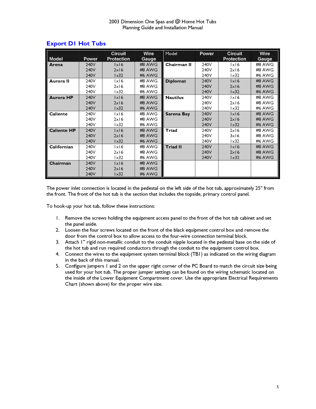
5.Configure jumpers 1 and 2 on the upper right corner of the PC Board to match the circuit size being used for your hot tub. The proper jumper settings can be found on the wiring schematic located on the inside of the Lower Equipment Compartment cover. Use the appropriate Electrical Requirements Chart (shown above) for the proper wire size.
5
