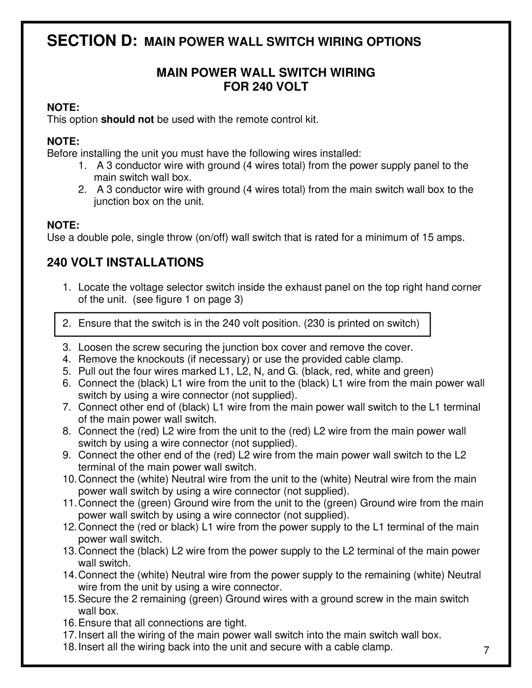
SECTION D: MAIN POWER WALL SWITCH WIRING OPTIONS

MAIN POWER WALL SWITCH WIRING

FOR 240 VOLT

NOTE:

This option should not be used with the remote control kit.

NOTE:

Before installing the unit you must have the following wires installed:

1.A 3 conductor wire with ground (4 wires total) from the power supply panel to the main switch wall box.

2.A 3 conductor wire with ground (4 wires total) from the main switch wall box to the junction box on the unit.

NOTE:

Use a double pole, single throw (on/off) wall switch that is rated for a minimum of 15 amps.

240 VOLT INSTALLATIONS

1.Locate the voltage selector switch inside the exhaust panel on the top right hand corner of the unit. (see figure 1 on page 3)

2.Ensure that the switch is in the 240 volt position. (230 is printed on switch)

3.Loosen the screw securing the junction box cover and remove the cover.

4.Remove the knockouts (if necessary) or use the provided cable clamp.

5.Pull out the four wires marked L1, L2, N, and G. (black, red, white and green)

6.Connect the (black) L1 wire from the unit to the (black) L1 wire from the main power wall switch by using a wire connector (not supplied).

7.Connect other end of (black) L1 wire from the main power wall switch to the L1 terminal of the main power wall switch.

8.Connect the (red) L2 wire from the unit to the (red) L2 wire from the main power wall switch by using a wire connector (not supplied).

9.Connect the other end of the (red) L2 wire from the main power wall switch to the L2 terminal of the main power wall switch.

10.Connect the (white) Neutral wire from the unit to the (white) Neutral wire from the main power wall switch by using a wire connector (not supplied).

11.Connect the (green) Ground wire from the unit to the (green) Ground wire from the main power wall switch by using a wire connector (not supplied).

12.Connect the (red or black) L1 wire from the power supply to the L1 terminal of the main power wall switch.

13.Connect the (black) L2 wire from the power supply to the L2 terminal of the main power wall switch.

14.Connect the (white) Neutral wire from the power supply to the remaining (white) Neutral wire from the unit by using a wire connector.

15.Secure the 2 remaining (green) Ground wires with a ground screw in the main switch wall box.

16.Ensure that all connections are tight.

17.Insert all the wiring of the main power wall switch into the main switch wall box.

18. Insert all the wiring back into the unit and secure with a cable clamp.

7


Page 9
Image 9
Dimplex BF33ST/DX, BF39ST/DX manual Section D Main Power Wall Switch Wiring Options For 240 Volt, Volt Installations

BF33ST/DX, BF39ST/DX specifications

The Dimplex BF39ST/DX and BF33ST/DX electric fires are innovative heating solutions that combine stylish design with advanced technology. Both models are part of Dimplex's extensive range of electric fires, designed to offer both functionality and aesthetic appeal, making them ideal for modern homes.

The BF39ST/DX model features a larger viewing area with a 39-inch width, while the BF33ST/DX offers a slightly smaller 33-inch width. This provides homeowners with flexibility when selecting the right size for their living spaces. Both models are designed to fit seamlessly into any room, offering a contemporary and appealing look that enhances the existing décor.

One of the standout features of these electric fires is the realistic 3D flame effect, Dimplex's patented Opti-myst technology. This advanced technology creates a lifelike flame and smoke effect using water vapor, providing an ambiance that closely resembles that of a traditional wood-burning fire. The flames can be adjusted for intensity, allowing users to customize the experience according to their preferences.

In terms of heating efficiency, both the BF39ST/DX and BF33ST/DX come with a 2kW fan heater that allows for rapid warming of spaces. Users can choose between two heat settings, enabling efficient temperature control and energy savings. This feature is particularly useful during colder months when immediate warmth is a priority.

Both models are equipped with a remote control, providing convenience for users to adjust settings from the comfort of their seat. This feature includes a timer function, allowing users to set the fire to operate for a specific duration or program it to turn off automatically.

Safety is paramount, and Dimplex has integrated essential safety features into both models. The fires are designed with an auto shut-off function that activates if the heater overheats, ensuring peace of mind for users.

Another notable characteristic is the ease of installation. The BF39ST/DX and BF33ST/DX can be wall-mounted or inset, providing flexibility in installation options to suit various home layouts. Their lightweight design simplifies repositioning, making it easy to change the fire's location if desired.

In summary, the Dimplex BF39ST/DX and BF33ST/DX electric fires offer a perfect blend of modern design, advanced heating technology, and user-friendly features. With their realistic flame effects, efficient heating, safety mechanisms, and flexibility in installation, these electric fires are an excellent heating solution for any contemporary living space.