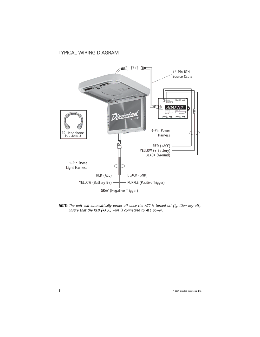
TYPICAL WIRING DIAGRAM
13-Pin DIN
 Source Cable
|
|
|
| A (R) | A (L) | V |
|
|
|
| OUT |
| |
|
|
|
|
| ||
|
|
|
|
| ||
13 | PIN | ADAPTOR |
| |||
TO MONITOR |
|
|
|
|
| |
|
| ADAPTORS |
| SERIAL NO. |
| |
|
| INPUT |
|
|
| |
|
| FUSE 2A |
|
| MADE IN TAIWAN | |
|
| IN 1 |
|
| IN 2 |
|
| V | A (L) | A (R) | V | A (L) | A (R) |
IR Headphone | ||
Harness | ||
(Optional) |
RED (+ACC)
YELLOW (+ Battery)
BLACK (Ground)
Light Harness
RED (ACC) | BLACK (GND) |
YELLOW (Battery B+) | PURPLE (Positive Trigger) |
GRAY (Negative Trigger)
NOTE: The unit will automatically power off once the ACC is turned off (ignition key off). Ensure that the RED (+ACC) wire is connected to ACC power.
8 | © 2004 Directed Electronics, Inc. |