Connections and Indicator
DC 12V IN REMOTE | VIDEO/AUDIO IN | VIDEO/AUDIO OUT |
| | DC 12V OUT | | | DIVERSITY ANTENNA INPUT | | | |
| | | | | | | | | | | | | |
| | | | | | | | | | | | | |
| | | | | | | | | | | | | |
| | | | | | | | | | | | | |
| | | | | | | | | | | | | |
| | | | | | | | | | | | | |
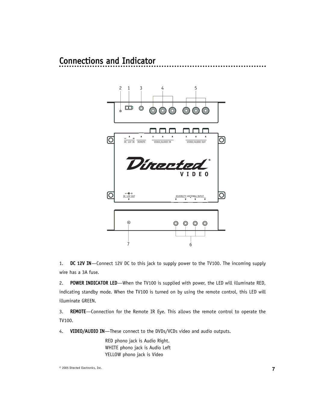
1.DC 12V IN—Connect 12V DC to this jack to supply power to the TV100. The incoming supply wire has a 3A fuse.
2.POWER INDICATOR LED—When the TV100 is supplied with power, the LED will illuminate RED, indicating standby mode. When the TV100 is turned on by using the remote control, this LED will
illuminate GREEN.
3.REMOTE—Connection for the Remote IR Eye. This allows the remote control to operate the
TV100.
4.VIDEO/AUDIO IN—These connect to the DVDs/VCDs video and audio outputs.
RED phono jack is Audio Right.
WHITE phono jack is Audio Left
YELLOW phono jack is Video
© 2005 Directed Electronics, Inc. | 7 |
|