ASSEMBLY
Assembly Instructions
Tools Required: |
|
Ratchet | (2) 3/4" Wrench |
Torque Wrench | 3/4" Socket |
1/2" Wrench | Flat Screw Driver |
1/2" Socket | (2) 1” Wrench - open end |
9/16" Wrench |
|
9/16" Socket |
|
RAM/RAM MAG
1.Remove clamshell from crate.
2.Remove two 5/16 x 3/4 carriage bolts from the lower flange of the rear guard on the mower.
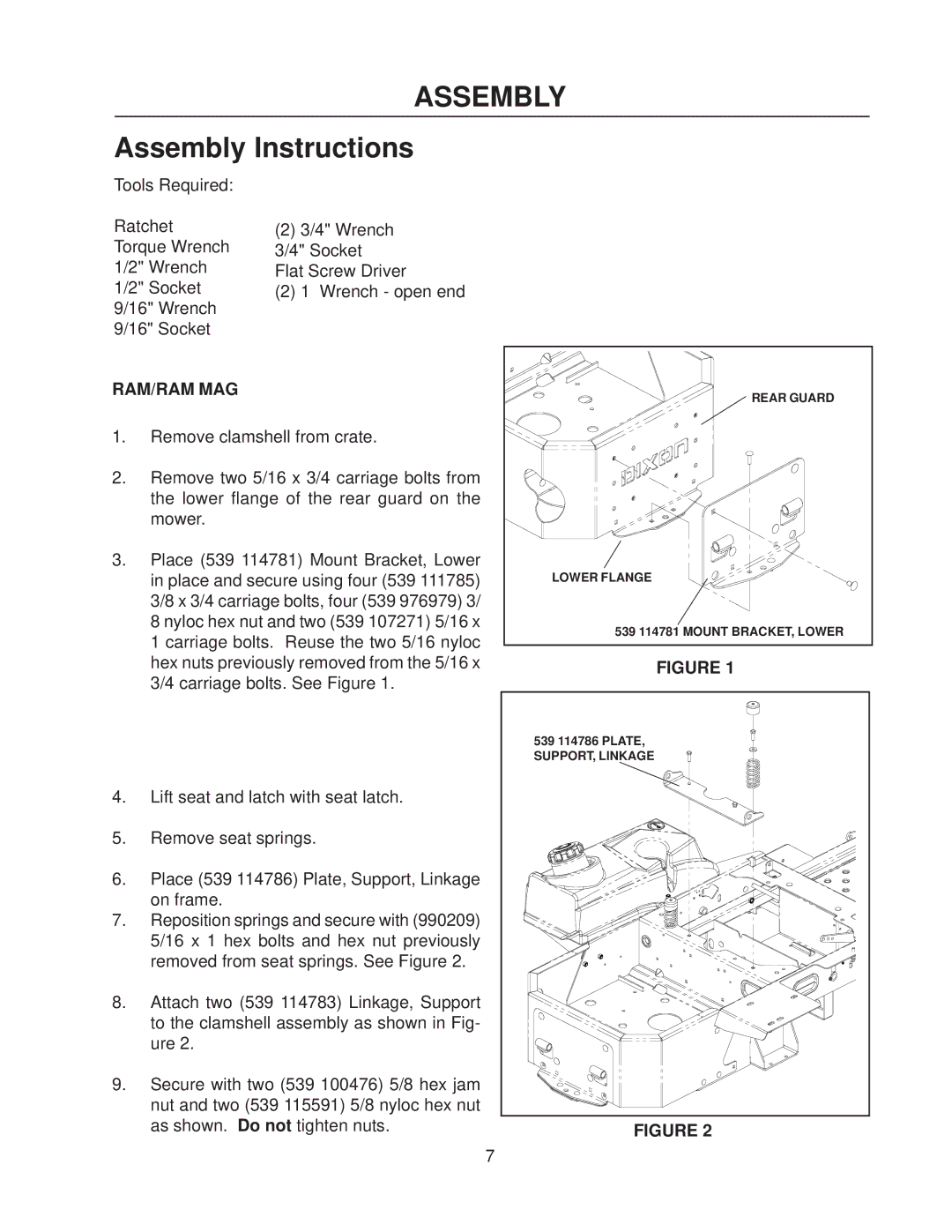
3.Place (539 114781) Mount Bracket, Lower in place and secure using four (539 111785) 3/8 x 3/4 carriage bolts, four (539 976979) 3/ 8 nyloc hex nut and two (539 107271) 5/16 x 1 carriage bolts. Reuse the two 5/16 nyloc hex nuts previously removed from the 5/16 x 3/4 carriage bolts. See Figure 1.
4.Lift seat and latch with seat latch.
5.Remove seat springs.
6.Place (539 114786) Plate, Support, Linkage on frame.
7.Reposition springs and secure with (990209) 5/16 x 1 hex bolts and hex nut previously removed from seat springs. See Figure 2.
8.Attach two (539 114783) Linkage, Support to the clamshell assembly as shown in Fig- ure 2.
9.Secure with two (539 100476) 5/8 hex jam nut and two (539 115591) 5/8 nyloc hex nut as shown. Do not tighten nuts.
REAR GUARD |
LOWER FLANGE |
539 114781 MOUNT BRACKET, LOWER |
FIGURE 1
539 114786 PLATE, |
SUPPORT, LINKAGE |
FIGURE 2
7
