DIXON INDUSTRIES, INC A BLOUNT COMPANY
AIRPORT INDUSTRIAL PARK PO BOX 1569
COFFEYVILLE KS 67337 O945 316 251 2OOO
FAX 316 251 4117
TECHNICAL DATA BROCHURE
Mode1 3O4
IMPORTANT - READ OPERATOR'S MANUAL BEFORE OPERATING OR MAKING ADJUSTMENTS
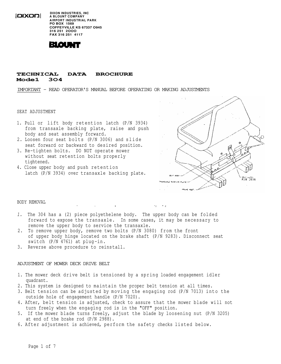
SEAT ADJUSTMENT
1.Pull or lift body retention latch (P/N 3934) from transaxle backing plate, raise and push body and seat assembly forward.
2.Loosen four seat bolts (P/N 3006) and slide seat forward or backward to desired position.
3.
4. Close upper body and push retention
latch (P/N 3934) over transaxle backing plate.
BODY REMOVAL
' | - | • | 'i | " £ |
1.The 304 has a (2) piece polyethelene body. The upper body can be folded forward to expose the transaxle. In some cases, it may be necessary to remove the upper body to service the transaxle.
2.To remove upper body, remove two bolts (P/N 3080) from the front
of upper body hinge located on the brake shaft (P/N 9283). Disconnect seat switch (P/N 4761) at
3.Reverse above procedure to reinstall.
ADJUSTMENT OF MOWER DECK DRIVE BELT
1.The mower deck drive belt is tensioned by a spring loaded engagement idler quadrant.
2.This system is designed to maintain the proper belt tension at all times.
3.Belt tension can be adjusted by moving the engaging rod (P/N 7013) into the outside hole of engagement handle (P/N 7020).
4.After, belt tension is adjusted, check to assure that the mower blade will not turn freely when the engaging rod is in the "OFF" position.
5.If the mower blade turns freely, adjust the blade by loosening nut (P/N 3205) at end of the brake rod (P/N 2988).
6.After adjustment is achieved, perform the safety checks listed below.
Page 1 of 7