Manuals
/
Dixon
/
Lawn and Garden
/
Lawn Mower
Dixon
501
manual
Models:
501
1
35
35
Download
35 pages
29.72 Kb
28
29
30
31
32
33
34
35
Troubleshooting
Install
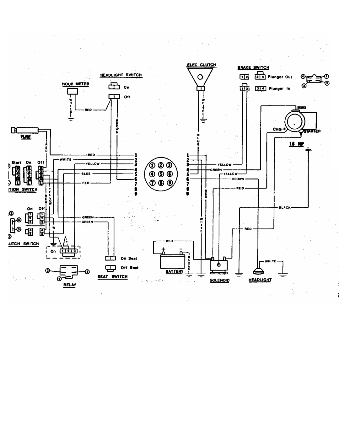
Broken wiring Repair
Warranty
Dimension
Maintenance
SET UP and Service
Seat Assembly Instructions
Repeat procedure on right side
Forward lever stop adjustment
Page 35
Image 35
Page 34
Page 35
Page 35
Image 35
Page 34
Page 35
Contents
Page
Troubleshooting
Safety
Warranty Policy Specifications SET UP and Service
Care and Maintenance
Important Read Carefully
See your dealer for warranty service, parts and repairs
Satisfactory use of this product
Always look behind you before backing up
Never carry passengers
Safety Safety Reminders Read Carefully Before Operation
Page
Warranty Policy
What is not covered by Dixon Industries, Inc
Product updates or improvements
Blade Drive Warner electric clutch
Dimensions Width Height Length
Specifications Subject to Change Without Notice
Aft
SET UP and Service
Insert the 2 cover. Firmly body is raised
Seat Assembly Instructions
Repeat procedure on right side
Position mower deck under chassis
Mower Deck Installation
Leveling the Deck
Mower Deck Leveling Procedure
Leveling Principals
Final Preparation
Cells that are low
No shifting or clutching required
Fuse Block
Throttle Control Lever
Mqker Deck CUT Height Lift Lever
Blade Drive
Care and Maintenance Model
Belt Tension
Reverse procedure to re-install deck assembly
Cutter Blade Removal
Care and Maintenance Model
Repeat above procedures on opposite hydrostat
Page
Adjustment Points for T-BOX Belt Tension
Forward lever stop adjustment
OIL Recommendations
Each front wheel caster
Primary and final drive
Engine manufacturer
Care and Maintenance Model Cleaning the Mower
Ground speed Reduce mowing speed
Loose belts Adjust per operators Manual
Unlevel mower deck Adjust per operators Manual
Check and adjust as
On one side or Manual Other
Mower pulls to one Drive adjustment
Repair Loss of drive power
Side or the other Manual
Broken wiring Repair
Battery Required Battery water low
Mower Battery discharge
Low battery condition
Illustration Mower Deck Assembly 50 Model
Illustration Body Assembly Model
Illustration Transmission Assembly Model
Illustration -Chassis Assembly Model
ZTR 501 Parts List PART# Description
Swivel Bracket Control Lever Right
ZTR 501 Pasts List PART# Description
Top
Page
Image
Contents