Connection to the ports
Connection to the ports
| A | B |
|
|
|
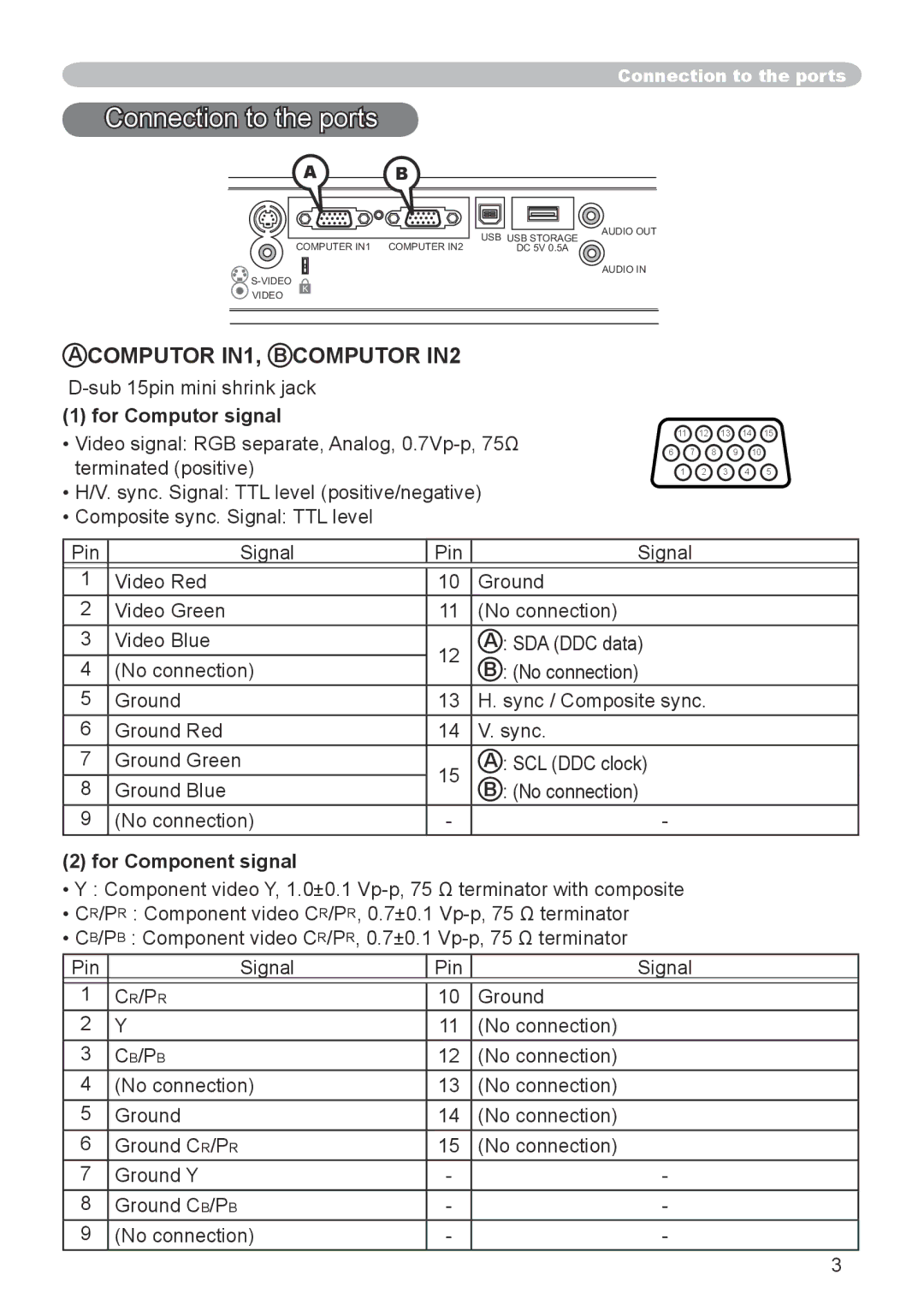
| USB | USB STORAGE | AUDIO OUT |
| COMPUTER IN1 |
| ||
| COMPUTER IN2 | DC 5V 0.5A |
| |
|
|
| AUDIO IN | |
K |
|
|
| |
VIDEO |
|
|
|
|
A COMPUTOR IN1, B COMPUTOR IN2
(1) for Computor signal
•Video signal: RGB separate, Analog,
•H/V. sync. Signal: TTL level (positive/negative)
•Composite sync. Signal: TTL level
11 12 13 14 15
6 7 8 9 10
1 2 3 4 5
Pin | Signal | Pin | Signal | |
|
|
|
| |
1 | Video Red | 10 | Ground | |
2 | Video Green | 11 | (No connection) | |
3 | Video Blue | 12 | A : SDA (DDC data) | |
4 | (No connection) | B : (No connection) | ||
| ||||
5 | Ground | 13 | H. sync / Composite sync. | |
6 | Ground Red | 14 | V. sync. | |
7 | Ground Green | 15 | A : SCL (DDC clock) | |
8 | Ground Blue | B : (No connection) | ||
| ||||
9 | (No connection) | - | - |
(2) for Component signal
•Y : Component video Y, 1.0±0.1
•CR/PR : Component video CR/PR, 0.7±0.1
•CB/PB : Component video CR/PR, 0.7±0.1
Pin | Signal | Pin | Signal |
|
|
|
|
1 | CR/PR | 10 | Ground |
2 | Y | 11 | (No connection) |
3 | CB/PB | 12 | (No connection) |
4 | (No connection) | 13 | (No connection) |
5 | Ground | 14 | (No connection) |
6 | Ground CR/PR | 15 | (No connection) |
7 | Ground Y | - | - |
8 | Ground CB/PB | - | - |
9 | (No connection) | - | - |