Arrangement

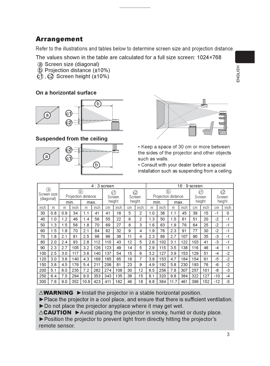
Refer to the illustrations and tables below to determine screen size and projection distance.

The values shown in the table are calculated for a full size screen: 1024×768 a Screen size (diagonal)

bProjection distance (±10%)

c1 , c2 Screen height (±10%)

ENGLISH

On a horizontal surface

Suspended from the ceiling


• Keep a space of 30 cm or more between


the sides of the projector and other objects


such as walls.


• Consult with your dealer before a special


installation such as suspending from a ceiling.


a


4 : 3 screen


16 : 9 screen


b


c1


c2


b


c1


c2


Screen size


(diagonal)

Projection distance

Screen


Screen

Projection distance

Screen

Screen


min.


max.

height


height

min.


max.

height

height


inch

m

m

inch


m

inch

cm


inch


cm


inch

m

inch


m


inch

cm


inch

cm


inch


30

0.8

0.9

34


1.1

41

41


16


5


2

1.0

38


1.1


45

39


15

-1


0


40

1.0

1.2

46


1.4

56

55


22


6


2

1.3

50


1.5


61

51


20

-2


-1


50

1.3

1.5

58


1.8

70

69


27


8


3

1.6

63


1.9


76

64


25

-2


-1


60

1.5

1.8

70


2.1

84

82


32


9


4

1.9

76


2.3


91

77


30

-2


-1


70

1.8

2.1

81


2.5

98

96


38


11


4

2.3

89


2.7


107

90


35

-3


-1


80

2.0

2.4

93


2.8

112

110


43


12


5

2.6

102


3.1


122

103


41

-3


-1


90

2.3

2.7

105


3.2

126

123


49


14


5

2.9

115


3.5


138

116


46

-4


-1


100

2.5

3.0

117


3.6

140

137


54


15


6

3.2

127


3.9


153

129


51

-4


-2


120

3.0

3.6

140


4.3

169

165


65


18


7

3.9

153


4.7


184

154


61

-5


-2


150

3.8

4.5

176


5.4

211

206


81


23


9

4.9

192


5.8


230

193


76

-6


-2


200

5.1

6.0

235


7.2

282

274


108


30


12

6.5

256


7.8


307

257


101

-8


-3


250

6.4

7.5

294


9.0

353

343


135


38


15

8.1

320


9.8


384

322


127

-10


-4


300

7.6

9.0

352


10.8

423

411


162


46


18

9.8

384


11.7


461

386


152

-12


-5

WARNING ►Install the projector in a stable horizontal position.

►Place the projector in a cool place, and ensure that there is sufficient ventilation. ►Do not place the projector anyplace where it may get wet.

CAUTION ►Avoid placing the projector in smoky, humid or dusty place. ►Position the projector to prevent light from directly hitting the projector’s remote sensor.

Page 3
Image 3
Dukane 8912H, 8916 user manual Arrangement, On a horizontal surface Suspended from the ceiling

8912H, 8916 specifications

Dukane is well-regarded for producing advanced ultrasonic welding equipment, and among its notable offerings are the Dukane 8916 and 8912H models. These ultrasonic plastic welding machines are engineered for optimal performance in various industrial applications, making them valuable assets for manufacturers.

The Dukane 8916 model is designed with versatility in mind. Equipped with a robust ultrasonic generator, it utilizes a frequency of 20 kHz, delivering consistent and efficient energy to facilitate the welding process. This model features a large operating window, allowing for flexibility in the size and type of parts being processed. Its transducer ensures effective energy conversion, resulting in a strong molecular bond between plastic components. The 8916 is particularly suitable for applications in the automotive and medical industries, where precision welding is essential.

On the other hand, the Dukane 8912H is tailored for high-speed production environments. This model boasts a compact design, making it ideal for integration into automated systems. Its improved cooling technology enhances operational efficiency, reducing downtime during production. The 8912H also offers user-friendly controls, which simplify the setup and monitoring of the welding process. This model is especially effective in applications such as packaging and electronics manufacturing, where rapid cycle times are a necessity.

Both models are equipped with advanced monitoring features that ensure the quality of the welds produced. They provide real-time feedback on the welding process, enabling operators to make necessary adjustments instantly. This technology not only enhances product quality but also minimizes waste, contributing to more sustainable manufacturing practices.

Another standout characteristic of the Dukane 8916 and 8912H models is their compatibility with multiple tooling options. This flexibility allows manufacturers to adapt the machines for various applications, whether it’s welding, cut-and-seal, or embossing. The ability to easily switch between different tools maximizes productivity and efficiency on the production floor.

In summary, the Dukane 8916 and 8912H ultrasonic welders are prominent models that provide advanced features, precision, and adaptability for diverse industrial applications. With their strong performance capabilities and state-of-the-art technology, these machines continue to set a standard for ultrasonic welding excellence in manufacturing environments.