DEM 313 specifications
The Dynacord DEM 313 is a versatile and powerful audio system designed for professional sound reinforcement applications. Renowned for its superior sound quality, exceptional durability, and advanced features, this unit has become a preferred choice for touring, live events, and installation.One of the standout features of the DEM 313 is its robust design, engineered to withstand the rigors of live sound environments. The rugged housing protects the internal components, ensuring reliability during demanding performances. The unit is also lightweight, making it easier for audio technicians to transport and install.
The DEM 313 incorporates a state-of-the-art digital signal processing (DSP) engine, providing precise control over audio signals. This allows users to customize sound according to specific venue requirements. The DSP offers a variety of presets and user-defined parameters, including parametric equalization, crossover settings, and delay adjustments. These features enable optimal tuning to achieve clarity and balance in sound reproduction.
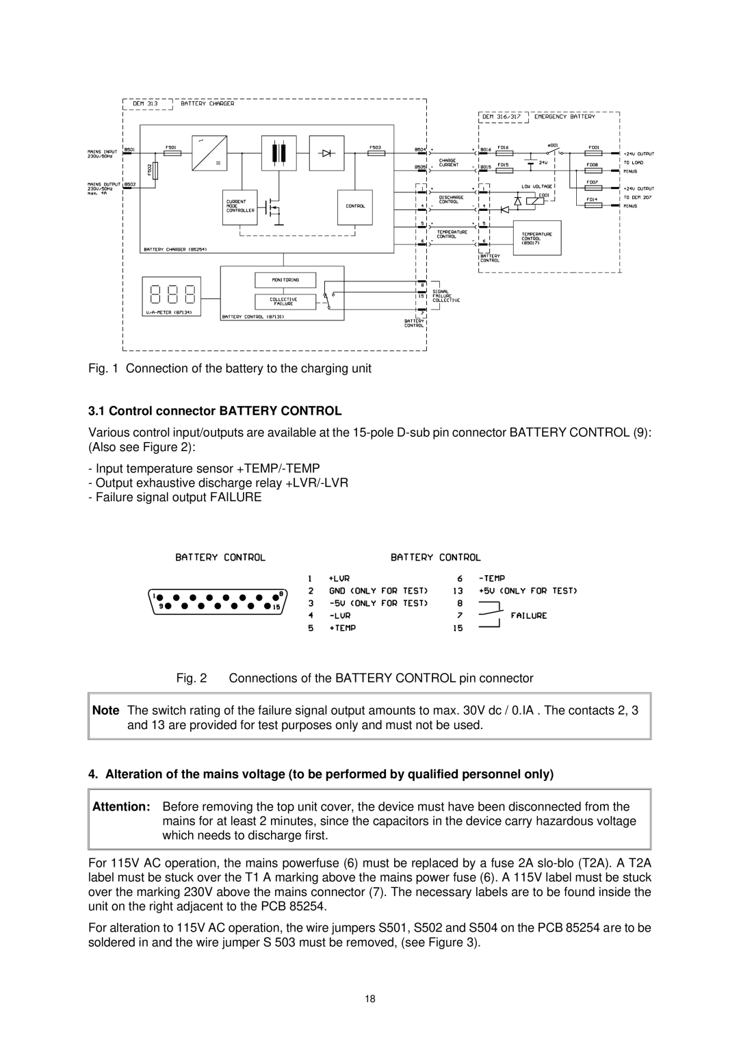
Equipped with multiple input and output options, the DEM 313 can handle a wide range of audio sources. Its configuration includes both analog and digital inputs, allowing seamless integration with various audio equipment. Additionally, the device supports network connectivity, making it compatible with modern audio systems and enabling remote control and monitoring capabilities.
The unit also features comprehensive metering and monitoring tools, providing real-time feedback on audio levels and performance. This ensures that sound engineers can make timely adjustments to maintain sound quality throughout a performance.
User-friendly interfaces and intuitive controls make the DEM 313 accessible to both novice and experienced sound professionals. The display panel presents essential information at a glance, streamlining operation during live events. Furthermore, built-in safety features protect the system from overload and overheating, ensuring consistent performance.
In summary, the Dynacord DEM 313 stands out in the competitive landscape of audio reinforcement technology. With its robust construction, advanced digital signal processing, versatile connectivity options, and user-friendly operation, it is an excellent solution for live sound applications, installations, and entertainment venues. The DEM 313 continues to set a benchmark in professional audio systems, delivering exceptional sound quality and reliability for audio professionals worldwide.

