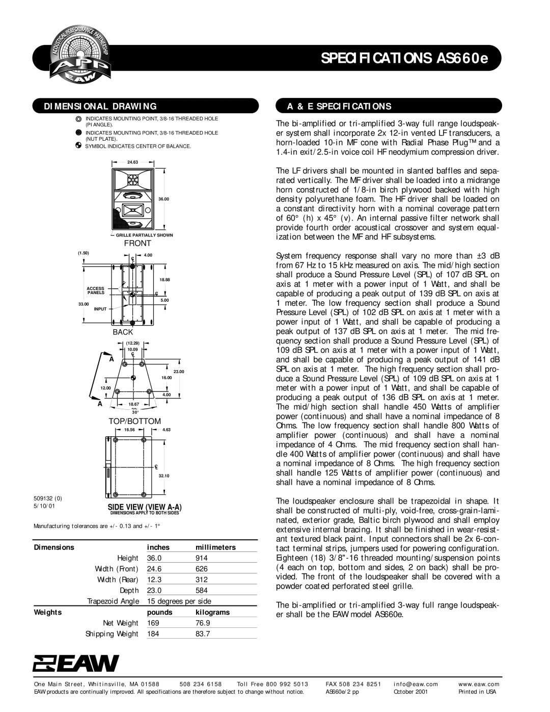
DIMENSIONAL DRAWING
INDICATES MOUNTING POINT,
INDICATES MOUNTING POINT,
SYMBOL INDICATES CENTER OF BALANCE.
| 24.63 |
| 36.00 |
| GRILLE PARTIALLY SHOWN |
| FRONT |
(1.50) | 4.00 |
| |
| C |
| L |
| 18.88 |
ACCESS |
|
PANELS | C |
| L |
33.00 | 5.00 |
| |
INPUT |
|
BACK
|
| (12.29) |
|
|
|
| 10.09 |
|
|
|
| C |
|
|
| A | L |
|
|
|
|
|
| |
|
|
| 23.00 |
|
|
|
| 16.00 |
|
12.00 |
|
|
| |
|
|
| 4.00 |
|
A |
| 18.67 |
|
|
|
| 30¡ |
|
|
|
| 30° |
|
|
| TOP/BOTTOM |
| ||
|
| 16.56 | 4.63 |
|
|
|
| C |
|
|
|
| L |
|
|
|
| 32.10 |
|
509132 (0) |
|
|
|
|
5/10/01 | SIDE VIEW (VIEW |
| ||
| DIMENSIONS APPLY TO BOTH SIDES |
| ||
Manufacturing tolerances are +/- 0.13 and +/- 1° |
| |||
Dimensions |
|
| inches | millimeters |
|
| Height | 36.0 | 914 |
Width (Front) | 24.6 | 626 | ||
Width (Rear) | 12.3 | 312 | ||
|
| Depth | 23.0 | 584 |
Trapezoid Angle | 15 degrees per side | |||
Weights |
|
| pounds | kilograms |
| Net Weight | 169 | 76.9 | |
Shipping Weight | 184 | 83.7 | ||
SPECIFICATIONS AS660e
A & E SPECIFICATIONS
The
The LF drivers shall be mounted in slanted baffles and sepa- rated vertically. The MF driver shall be loaded into a midrange horn constructed of
System frequency response shall vary no more than ±3 dB from 67 Hz to 15 kHz measured on axis. The mid/high section shall produce a Sound Pressure Level (SPL) of 107 dB SPL on axis at 1 meter with a power input of 1 Watt, and shall be capable of producing a peak output of 139 dB SPL on axis at 1 meter. The low frequency section shall produce a Sound Pressure Level (SPL) of 102 dB SPL on axis at 1 meter with a power input of 1 Watt, and shall be capable of producing a peak output of 137 dB SPL on axis at 1 meter. The mid fre- quency section shall produce a Sound Pressure Level (SPL) of 109 dB SPL on axis at 1 meter with a power input of 1 Watt, and shall be capable of producing a peak output of 141 dB SPL on axis at 1 meter. The high frequency section shall pro- duce a Sound Pressure Level (SPL) of 109 dB SPL on axis at 1 meter with a power input of 1 Watt, and shall be capable of producing a peak output of 136 dB SPL on axis at 1 meter. The mid/high section shall handle 450 Watts of amplifier power (continuous) and shall have a nominal impedance of 8 Ohms. The low frequency section shall handle 800 Watts of amplifier power (continuous) and shall have a nominal impedance of 4 Ohms. The mid frequency section shall han- dle 400 Watts of amplifier power (continuous) and shall have a nominal impedance of 8 Ohms. The high frequency section shall handle 125 Watts of amplifier power (continuous) and shall have a nominal impedance of 8 Ohms.
The loudspeaker enclosure shall be trapezoidal in shape. It shall be constructed of
The
One | Main Street, Whitinsville, MA 01588 | 508 234 6158 | Toll Free 800 992 5013 | FAX 508 234 8251 | info@eaw. com | www. eaw. com |
EAW | products are continually improved. All specifications are therefore subject to change without notice. | AS660e/2 pp | October 2001 | Printed in USA | ||