CM-1 specifications
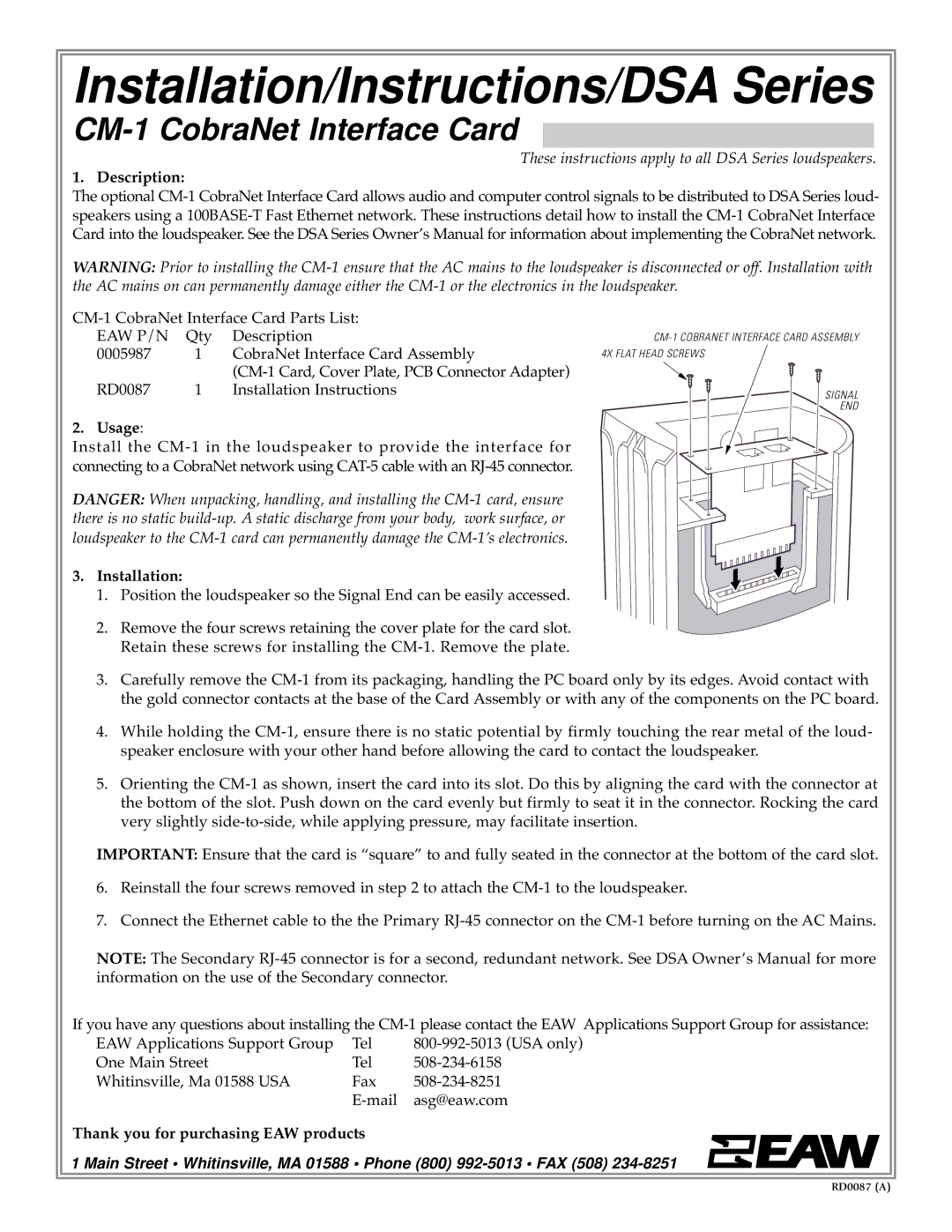
The EAW CM-1 is a standout in the world of professional audio systems, designed for musicians, sound engineers, and event organizers seeking high-quality sound reproduction. EAW, or Eastern Acoustic Works, has a long history of delivering top-notch audio solutions, and the CM-1 is no exception. It embodies advanced technology and innovative design, making it a preferred choice for various live performance settings.One of the main features of the EAW CM-1 is its exceptional sound clarity. This is achieved through a carefully engineered driver arrangement that combines a high-frequency compression driver and a low-frequency transducer. The result is a balanced frequency response that ensures every note and vocal is delivered with stunning precision. This is particularly crucial in live settings where the clarity of sound can make or break a performance.
The CM-1 is also equipped with EAW's proprietary Waveguide technology, which enhances the control of high-frequency dispersion. This technology ensures that sound is distributed evenly across the audience, minimizing hot spots and dead zones. Musicians and sound engineers will appreciate the consistency of sound coverage, allowing for a more immersive experience for attendees.
In terms of build quality, the EAW CM-1 is constructed with durable materials designed to withstand the rigors of touring and repeated use. Its lightweight yet sturdy design allows for easy transportation and setup, making it an ideal choice for mobile applications. Additionally, the cabinet features integrated rigging points for suspension, providing flexibility in mounting options for various venue configurations.
The versatility of the CM-1 is also noteworthy. It can function as a standalone speaker in smaller venues, or it can be integrated into larger systems for enhanced sound reinforcement. This adaptability makes it suitable for a range of applications, from concerts and festivals to corporate events and theater productions.
Another technological highlight of the CM-1 is its compatibility with various audio processing systems. This ensures that it can integrate seamlessly with different mixing consoles and playback devices, offering users a high degree of flexibility in sound design and management.
In summary, the EAW CM-1 is a powerful and versatile speaker system that excels in delivering high-quality sound across various environments. Its prominent features like clarity, high-frequency dispersion control, durable construction, and adaptability ensure that it meets the demands of professionals in the audio industry. Whether used for a small gig or a large concert, the CM-1 stands as a reliable choice that elevates the audio experience.

