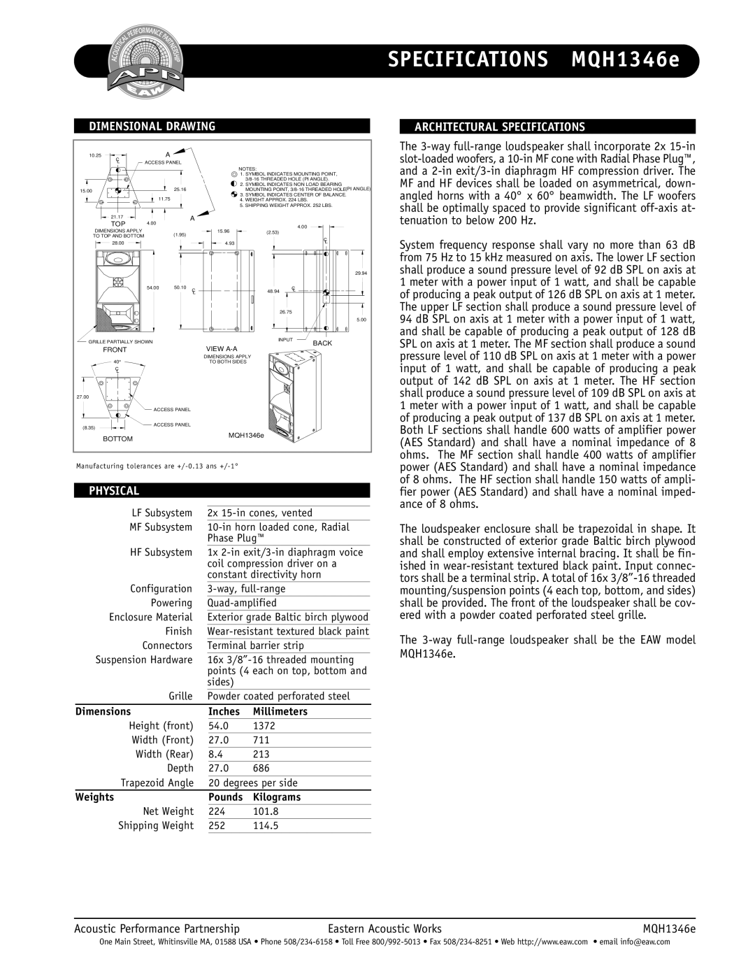
MQH1346e specifications
The EAW MQH1346e is a state-of-the-art loudspeaker designed for professional audio applications, particularly in live sound and installation settings. Known for its impressive sound quality and versatile deployment options, the MQH1346e offers distinct advantages for audio engineers and sound technicians.At the core of the MQH1346e's design is its cutting-edge technology, featuring a high-efficiency 14-inch low-frequency driver paired with a revolutionary 3-inch high-frequency compression driver. This combination delivers a powerful and clear sound reproduction across a wide frequency range. The loudspeaker is capable of producing sound textures that are vibrant and full, making it suitable for various music genres and spoken-word applications alike.
One of the key features of the EAW MQH1346e is its Phase Aligned Waveguide technology. This innovative design ensures that sound waves emitted from the loudspeaker maintain a consistent phase relationship, resulting in cohesive audio across the listening area. The advanced waveguide also aids in enabling a broad horizontal dispersion pattern, offering excellent coverage while minimizing the impact of room acoustics.
The loudspeaker is engineered with durability and reliability in mind, sporting a robust enclosure made from premium materials that withstand the rigors of touring and permanent installations. Its weather-resistant coating further enhances its outdoor usability, allowing for performances in various environmental conditions without sacrificing performance quality.
Connectivity is another strong suit of the MQH1346e. It comes equipped with a comprehensive selection of input and output options, accommodating various professional audio setups. The built-in digital signal processing (DSP) empowers users with extensive control over EQ settings, delay adjustments, and other audio management features. This flexibility is particularly advantageous in complex sound environments where precision tuning is essential.
In addition to sound quality and versatility, the EAW MQH1346e is designed for ease of use. The loudspeaker includes multiple rigging points, facilitating quick mounting and deployment for both fixed installations and mobile setups. Compatibility with various racks and flight cases further simplifies transport and storage.
In conclusion, the EAW MQH1346e is a remarkable loudspeaker that combines advanced technologies, robust construction, and user-friendly features. With its exceptional sound performance and flexibility, it becomes an invaluable asset for professionals in the audio industry, ensuring that any event or installation delivers an unforgettable auditory experience.

