21560065
nylon line head instructions
contents
1 - High Capacity Manual Trimmer Head w/Standard 10 mm x 1.25 Mounting Arbor
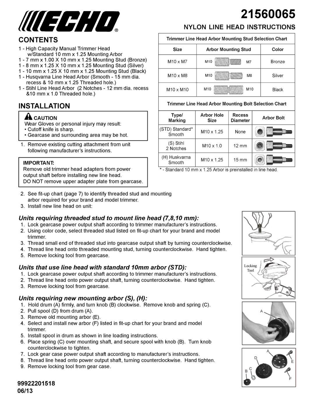
1 - 7 mm x 1.00 X 10 mm x 1.25 Mounting Stud (Bronze) 1 - 8 mm x 1.25 X 10 mm x 1.25 Mounting Stud (Silver)
1 - 10 mm x 1.25 X 10 mm x 1.25 Mounting Stud (Black) 1 - Husqvarna Line Head Arbor (Smooth - 15 mm dia.
recess & 10 mm x 1.25 Threaded hole.)
1 - Stihl Line Head Arbor (2 Notches - 12 mm dia. recess &10 mm x 1.0 Threaded hole.)
installation
![]() Caution
Caution
Wear Gloves or personal injury may result:
•Cutoff knife is sharp.
•Gearcase and surrounding area may be hot.
1.Remove existing cutting attachment from unit following manufacturer’s instructions.
IMPORTANT:
Remove old trimmer head adapters from power output shaft before installing new line head.
DO NOT remove upper adapter plate from gearcase.
2.See
3.Install new line head on unit:
Units requiring threaded stud to mount line head (7,8,10 mm):
1.Lock gearcase power output shaft according to trimmer manufacturer’s instructions.
2.Using color code, select threaded stud listed on
3.Thread small end of threaded stud into gearcase output shaft by turning counterclockwise.
4.Thread line head onto threaded mounting stud, turning counterclockwise. Hand tighten.
5.Remove locking tool from gearcase.
Units that use line head with standard 10mm arbor (STD):
1.Lock gearcase power output shaft according to trimmer manufacturer’s instructions.
2.Thread line head onto power output shaft, turning counterclockwise. Hand tighten.
3.Remove locking tool from gearcase.
Units requiring new mounting arbor (S), (H):
1.Hold drum (A) firmly, and turn knob (B) clockwise. Remove knob and spring (C).
2.Pull spool (D) from drum (A).
3.Remove old mounting arbor (E).
4.Select and install new arbor (F) listed in
5.Install spool in drum as shown in line loading instructions.
6.Place spring (C) over mounting shaft, and secure spool with knob (B). Turn knob counterclockwise to tighten.
7.Lock gear case power output shaft according to manufacturer’s instructions.
8.Thread line head onto power output shaft, turning counterclockwise. Hand tighten.
9.Remove locking tool from gear case.
99922201518
06/13