DESCRIPTION | ||||
|
|
|
|
|
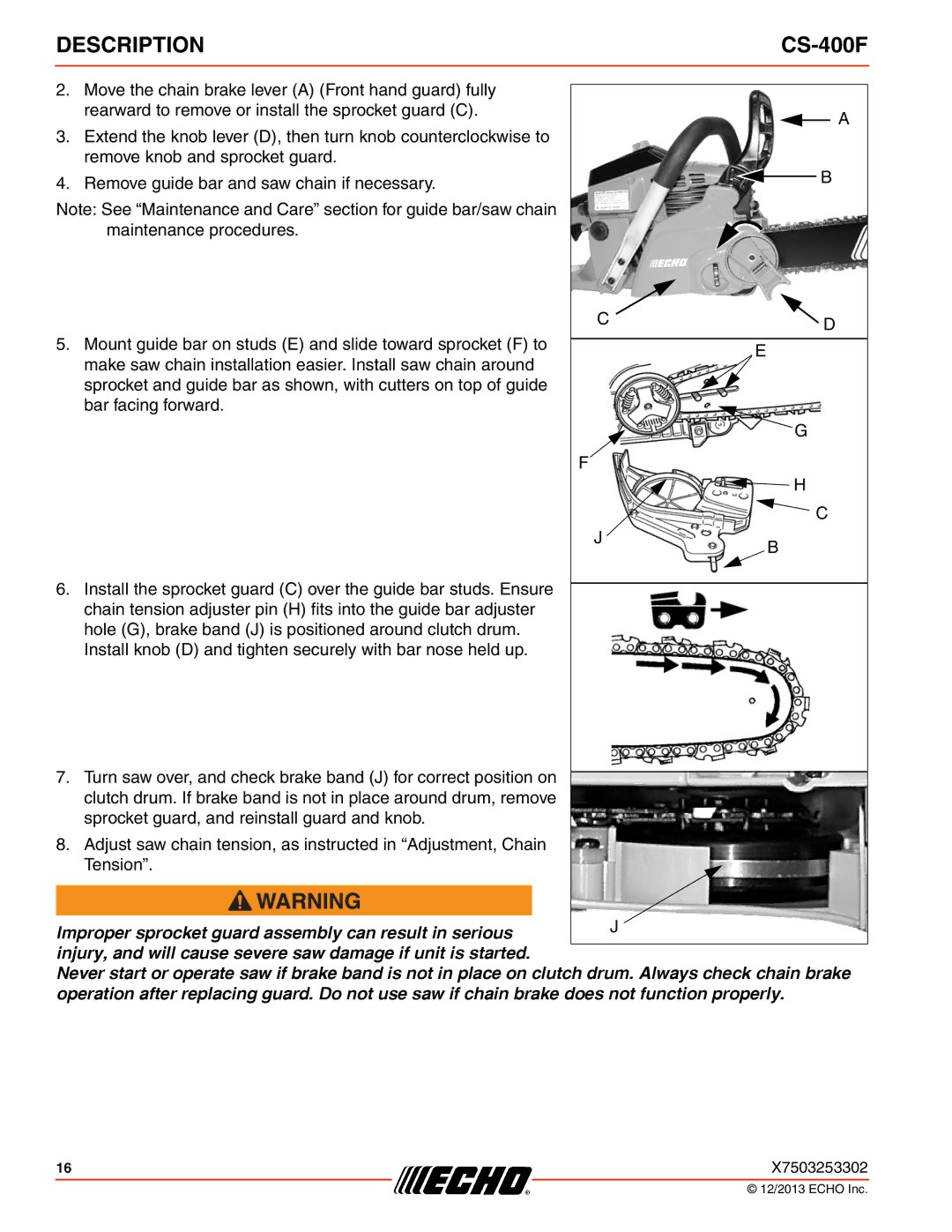
2. Move the chain brake lever (A) (Front hand guard) fully |
|
|
|
|
|
|
|
| |
rearward to remove or install the sprocket guard (C). |
|
|
| A |
|
|
|
| |
3.Extend the knob lever (D), then turn knob counterclockwise to remove knob and sprocket guard.
4. Remove guide bar and saw chain if necessary. |
| B |
| ||
|
|
Note: See “Maintenance and Care” section for guide bar/saw chain maintenance procedures.
| C | D |
|
| |
5. Mount guide bar on studs (E) and slide toward sprocket (F) to |
|
|
| E | |
make saw chain installation easier. Install saw chain around |
| |
|
| |
sprocket and guide bar as shown, with cutters on top of guide |
|
|
bar facing forward. |
|
|
|
| G |
| F |
|
|
| H |
|
| C |
| J | B |
|
|
6.Install the sprocket guard (C) over the guide bar studs. Ensure chain tension adjuster pin (H) fits into the guide bar adjuster hole (G), brake band (J) is positioned around clutch drum. Install knob (D) and tighten securely with bar nose held up.
7.Turn saw over, and check brake band (J) for correct position on clutch drum. If brake band is not in place around drum, remove sprocket guard, and reinstall guard and knob.
8.Adjust saw chain tension, as instructed in “Adjustment, Chain Tension”.
Improper sprocket guard assembly can result in serious | J |
| |
injury, and will cause severe saw damage if unit is started. |
|
Never start or operate saw if brake band is not in place on clutch drum. Always check chain brake operation after replacing guard. Do not use saw if chain brake does not function properly.
16 | X7503253302 |
© 12/2013 ECHO Inc.
