BATTERY IS PROBABLY DEPLETED. REMOVE UNIT FROM CEILING (SEE FIG 1) AND REPLACE BATTERY.
DO NOT ATTEMPT TO OPEN THE ALARM AS IT IS PERMANENTLY SEALED FOR SAFETY.
IF A NUISANCE ALARM OCCURS PRESS THE TEST/HUSH BUTTON TO SILENCE THE ALARM FOR 10 MINUTES.
UNIT WILL NOT FIT ON THE MOUNTING PLATE WITHOUT A BATTERY INSTALLED (EI181/184/186 ONLY)
TAMPERPROOF | MOUNTING PLATE |
CATCH | |
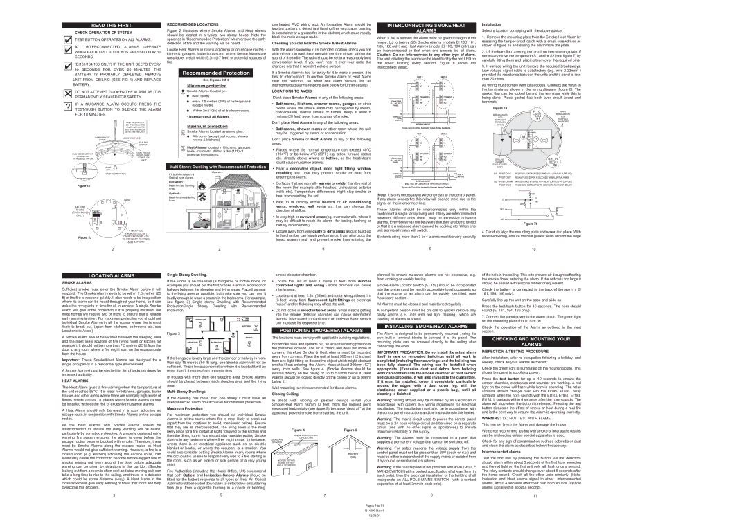
Recommended Protection
See Figures 2 & 3
Minimum protection
Smoke Alarms located on:-
each storey
every 7.5 metres (25ft) of hallways and escape routes
Within 3m (10th) of all bedroom doors.
- Interconnect all Alarms
Maximum protection
Smoke Alarms located as above plus:-
All rooms (except bathrooms, shower rooms & kitchens)
If a Smoke Alarm is too far away for it to wake a person, it is best to interconnect to another Smoke Alarm or Heat Alarm near the bedroom, so when one alarm senses fire, all interconnected alarms respond (see below for further details).
LOCATIONS TO AVOID
Don’t place Smoke Alarms in any of the following areas:
•Bathrooms, kitchens, shower rooms, garages or other rooms where the smoke alarm may be triggered by steam, condensation, normal smoke or fumes. Keep at least 6 metres (20 feet) away from sources of smoke.
Don’t place Heat Alarms in any of the following areas:
•Bathrooms, shower rooms or other room where the unit may be triggered by steam or condensation.
Don’t place Smoke or Heat Alarms in any of the following
| | UNIT 1 | UNIT 2 |
| | + | + |
| | IC | IC |
| | - | - |
| | COMMON | COMMON |
| COMPATIBLE | NO | NO |
| NC | NC |
| 10.5 - 30 VOLT |
| PANEL | | |
| +V | | |
| 0V | | |
| NORMALLY | | |
| OPEN | | |
| CIRCUIT | | |
INTERCONNECT
Figure 6a Circuit for Normally Open Relay Contacts
provided the resistance between the units and the panel is less |
than 20 ohms. |
All wiring must comply with local codes. Connect the wires to the terminals as shown in the wiring diagram (figure 6). The gasket flap can be tucked behind the terminals while this is being done. Place gasket flap back over circuit board and terminals.
Figure 7a
| | P C | MAIN |
BREAKAWAYS | | | BREAKAWAYS |
| | FOR |
FOR | | S1 |
STRAIGHT | | SURFACE |
| | MOUNTING |
THROUGH | | |
| | |
WIRING | | | |
| | COMMON | |
| P C | NO | |
| NC | |
| S1 NR R | |
| | S2 | |
LOCATING ALARMS
SMOKE ALARMS
Sufficient smoke must enter the Smoke Alarm before it will respond. The Smoke Alarm needs to be within 7.5 metres (25 ft) of the fire to respond quickly. It also needs to be in a position where its alarm can be heard throughout your home, so it can wake the occupants in time for all to escape. A single Smoke Alarm will give some protection if it is properly installed, but most homes will require two or more to ensure that a reliable early warning is given. For maximum protection you should put individual Smoke Alarms in all the rooms where fire is most likely to break out, (apart from kitchens, bathrooms etc. see Locations to Avoid).
A Smoke Alarm should be located between the sleeping area and the most likely sources of fire (living room or kitchen for example). It should not be more than 7.5 metres (25 ft) from the door to any room where a fire might start on the escape route from the house.
Important: These Smoke/Heat Alarms are designed for a single occupancy in a residential type environment.
A Smoke Alarm should be sited within 3m of bedroom doors for improved audibility.
HEAT ALARMS
The Heat Alarm gives a fire warning when the temperature at the unit reaches 58°C. It is ideal for kitchens, garages, boiler houses and other areas where there are normally high levels of fumes, smoke or dust i.e. places where Smoke Alarms cannot be installed without the risk of excessive nuisance alarms.
A Heat Alarm should only be used in a room adjoining an escape route, in conjunction with Smoke Alarms on the escape routes.
All the Heat Alarms and Smoke Alarms should be interconnected to ensure the early warning will be heard, particularly by somebody sleeping. A properly designed early warning fire system ensures the alarm is given before the escape routes become blocked with smoke. Therefore, there must be Smoke Alarms along the escape routes as Heat Alarms would not give sufficient warning. However, a fire in a closed room (e.g. kitchen) adjoining the escape route, can eventually cause the corridor to become smoke-logged due to smoke leaking out from around the door before adequate warning can be given by detectors in the corridor. (Smoke leaking out from a room is often cool and slow moving so it can take a long time to rise to the ceiling, and travel to a detector which could be some distance away). A Heat Alarm in the closed room will give early warning of fire in that room and help overcome this problem.
Single Storey Dwelling.
If the Home is on one level (a bungalow or mobile home for example) you should put the first Smoke Alarm in a corridor or hallway between the sleeping and living areas. Place it as near to the living area as possible, but make sure you can hear it loudly enough to wake a person in the bedrooms. (for example, see figure 3) Single storey Dwelling with Recommended ProtectionSingle Storey Dwelling with Recommended Protection
BEDROOM
KITCHEN
Figure 3
DINING
If the bungalow is very large and the corridor or hallway is more than say 15 metres (50 ft) long, one Smoke Alarm will not be sufficient. This is because no matter where it is located it will be more than 7.5 metres from potential fires.
In houses with more than one sleeping area, Smoke Alarms should be placed between each sleeping area and the living area.
Multi Storey Dwellings
If the dwelling has more than one storey it must have an interconnected alarm on each level for minimum protection.
Maximum Protection
For maximum protection you should put individual Smoke Alarms in all the rooms where fire is most likely to break out (apart from the locations to avoid, mentioned below). Ensure that they are all interconnected. The living room is the most likely place for a fire to start at night, followed by the kitchen and then the dining room. You should also consider putting Smoke Alarms in any bedrooms where fires might occur, for instance, where there is an electrical appliance such as an electric blanket or heater, or where the occupant is a smoker. You could also consider putting Smoke Alarms in any rooms where the occupant is unable to respond very well to a fire starting in the room, such as an elderly or sick person or a very young child.
Fire Authorities (including the Home Office, UK) recommend that both Optical and Ionisation Smoke Alarms should be fitted for the fastest response to all types of fires. An Optical Alarm should be located downstairs to detect slow smouldering fires (e.g. from a cigarette burning in a couch or bedding,
smoke detector chamber.
•Locate the unit at least 1 metre (3 feet) from dimmer controlled lights and wiring - some dimmers can cause interference.
•Locate unit at least 1.5m (5 feet) and route wiring at least 1m (3 feet) away from fluorescent light fittings as electrical “noise” and/or flickering may affect the unit.
•Do not locate in insect infested areas. Small insects getting into the smoke detector chamber can cause intermittent alarms. Insects and contamination on the Heat Alarm sensor can increase its response time.
POSITIONING SMOKE/HEATALARMS
The locations must comply with applicable building regulations.
Hot smoke rises and spreads out, so a central ceiling position is the preferred location. The air is “dead” and does not move in corners, therefore Smoke & Heat Alarms must be mounted away from corners. Place the unit at least 300mm (12 inches) from any light fitting or decorative object which might obstruct smoke / heat entering the Alarm. Keep at least 300mm (12”) away from walls. See figure 4. (Smoke Alarms should be located directly on the ceiling or up to 570mm below it. Heat Alarms should be located directly on the ceiling or up to 90mm below it).
Wall mounting is not recommended for these Alarms.
Sloping Ceiling
In areas with sloping or peaked ceilings install your Smoke/Heat Alarm 90mm (3 feet) from the highest point measured horizontally (see figure 5), because “dead air” at the apex may prevent smoke from reaching the unit.
IDEAL FOR CENTRE
OF CEILING
DEAD AIR
SPACES
900mm
(3 ft)
NEVER WITHIN 300mm OF ANY WALL / CORNER
planned to ensure nuisance alarms are not excessive, e.g. from cooking or weekly testing.
Smoke Alarm Locator Switch (EI 159) should be incorporated into the system and be readily accessible to all occupants so that the source of an alarm can be quickly identified. (see Accessory section).
All Alarms must be cleaned and maintained regularly.
A competent person must be on call to quickly remove any faulty alarms (i.e. units with red light flashing), which are causing all alarms to sound.
INSTALLING SMOKE/HEAT ALARMS
The Alarm is designed to be permanently mounted , using it’s own built-in terminal blocks to connect it to the panel. The mounting plate can be screwed directly to the ceiling after connecting the wires.
IMPORTANT PRECAUTION: Do not install the actual alarm itself in new or renovated buildings until all work is completed (including floor coverings) and the building has been fully cleaned. The wiring can be installed when appropriate. (Excessive dust and debris from building work can contaminate the smoke chamber or heat sensor and cause problems, it will also invalidate the guarantee). If it must be installed, cover it completely, particularly around the edges, with a dust cover (eg. with the elasticated cover supplied or a plastic bag), until all cleaning is finished.
Warning: Wiring should only be installed by an Electrician in accordance with current IEE wiring regulations for electrical installation. The installation must also be in accordance with the control panel instructions and the instructions in this leaflet.
Warning: The mains circuit used to power the control panel must be a 24 hour voltage circuit and be wired on a separate circuit (one with no other lights or applilances) to ensure maximum reliability of the supply.
Warning: The Alarms must be connected to a panel that supplies a permanent voltage that cannot be switched off.
Warning: For safety reasons the voltage supply from the control panel must not be greater than 30V (peak or d.c.) and must be either independent of the supply mains or isolated from it by double or reinforced insulations.
Warning: If the control panel is not provided with an ALL-POLE MAINS SWITCH (with a contact specification of at least 3mm in each pole), then the electrical installation of the building shall incorporate an ALL-POLE MAINS SWITCH, (with a contact separation of at least 3mm in each pole).
of the hole in the ceiling. This is to prevent air draughts affecting the smoke / heat entering the alarm. If the orifice is too large it should be sealed with silicone rubber or equivalent.
Check the battery is connected in the back of the alarm ( EI 181, 184, 186 only).
Carefully line up the unit on the base and slide on.
Press the test/hush button for 10 seconds. The horn should sound (EI 181, 184, 186 only).
7.Connect the panel power to the alarm circuit. The green light on the mounting plate should turn on.
Check the operation of the Alarm as outlined in the next section.
CHECKING AND MOUNTING YOUR
ALARMS
INSPECTION & TESTING PROCEDURE
After installation, after re-occupation following a holiday, and weekly, check all your Alarms as follows:
Check the green light is illuminated on the mounting plate. This shows the panel is supplying power.
Press the test button for up to 10 seconds to ensure the sensor chamber, electronics and sounder are working. A red light on the cover will flash while horn is sounding. The relay contacts should change over with the EI185, EI186 relay contacts when the horn sounds with the EI180, EI181, EI183, EI184, it contacts within 6 seconds after the horn sounds. The alarm will stop when the button is released. Pressing the test button simulates the effect of smoke or heat during a real fire and is the best way to ensure the Alarm is operating correctly.
WARNING: DO NOT TEST WITH FLAME.
This can set fire to the Alarm and damage the house.
We do not recommend testing with smoke or heat as the results can be misleading unless special apparatus is used.
Check for any sign of contamination such as cobwebs or dust and clean the alarm as described below if necessary.
Interconnected alarms
Test the first unit by pressing the button. All the detectors should alarm within about 5 seconds of the first horn sounding and the red light on the first unit only will flash once a second. The relay contacts should change over about 6 seconds after the horns sound. Check all the other units similarly. (Note: Ionisation and Heat alarms signal to other interconnected alarms, about 4 seconds after their own horn sounds. Optical alarms signal within about a second).