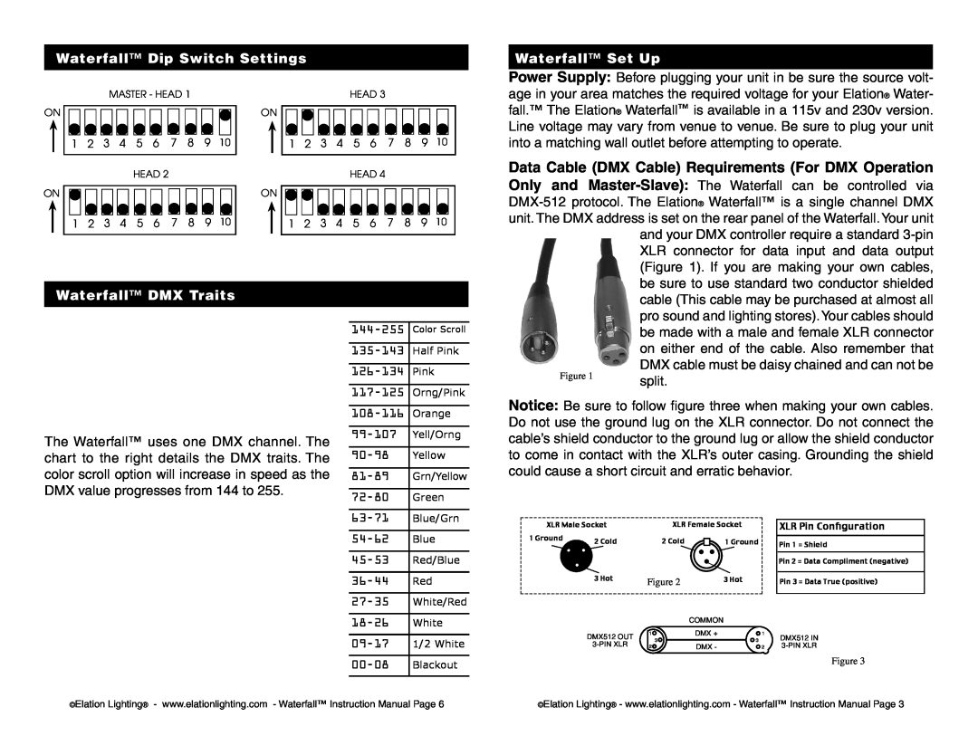
Waterfall™ Dip Switch Settings
Waterfall™ Set Up
ON
ON
MASTER - HEAD 1
|
|
|
|
|
|
|
|
|
|
|
|
|
|
|
|
|
|
|
|
|
|
|
|
|
|
|
|
|
|
|
|
|
|
|
|
|
|
|
|
|
|
1 | 2 | 3 | 4 | 5 | 6 | 7 | 8 | 9 | 10 |
| ||||||||||
|
|
|
|
|
|
|
|
|
|
|
|
|
|
|
|
|
|
|
|
|
HEAD 2
ON
ON
HEAD 3
|
|
|
|
|
|
|
|
|
|
|
|
|
|
|
|
|
|
|
|
|
|
|
|
|
|
|
|
|
|
|
|
|
|
|
|
|
|
|
|
|
|
1 | 2 | 3 | 4 | 5 | 6 | 7 | 8 | 9 | 10 |
| ||||||||||
|
|
|
|
|
|
|
|
|
|
|
|
|
|
|
|
|
|
|
|
|
HEAD 4
Power Supply: Before plugging your unit in be sure the source volt- age in your area matches the required voltage for your Elation® Water- fall.™ The Elation® Waterfall™ is available in a 115v and 230v version. Line voltage may vary from venue to venue. Be sure to plug your unit into a matching wall outlet before attempting to operate.
Data Cable (DMX Cable) Requirements (For DMX Operation Only and
1 | 2 | 3 | 4 | 5 | 6 | 7 | 8 | 9 | 10 | 1 | 2 | 3 | 4 | 5 | 6 | 7 | 8 | 9 | 10 |
Waterfall™ DMX Traits
The Waterfall™ uses one DMX channel. The chart to the right details the DMX traits. The color scroll option will increase in speed as the DMX value progresses from 144 to 255.
Color Scroll | |
|
|
Half Pink | |
|
|
Pink | |
|
|
Orng/Pink | |
|
|
Orange | |
|
|
Yell/Orng | |
|
|
Yellow | |
|
|
Grn/Yellow | |
|
|
Green | |
|
|
Blue/Grn |
and your DMX controller require a standard
Figure 1 | split. |
|
Notice: Be sure to follow figure three when making your own cables. Do not use the ground lug on the XLR connector. Do not connect the cable’s shield conductor to the ground lug or allow the shield conductor to come in contact with the XLR’s outer casing. Grounding the shield could cause a short circuit and erratic behavior.
Blue | |
|
|
Red/Blue | |
|
|
Red | |
|
|
White/Red | |
|
|
White | |
|
|
1/2 White | |
|
|
Blackout |
XLR Male Socket | XLR Female Socket |
| ||
1 Ground | 2 Cold | 2 Cold | 1 Ground |
|
|
| |||
| 3 Hot | Figure 2 | 3 Hot |
|
|
|
| COMMON |
|
| DMX512 OUT | 1 | DMX + | 1 |
| 3 | 3 |
| |
|
| |||
| 2 | DMX - | 2 | |
XLR Pin Configuration
Pin 1 = Shield
Pin 2 = Data Compliment (negative)
Pin 3 = Data True (positive)
DMX512 IN
Figure 3
©Elation Lighting® - www.elationlighting.com - Waterfall™ Instruction Manual Page 6 | ©Elation Lighting® - www.elationlighting.com - Waterfall™ Instruction Manual Page 3 |