U.S.A. and Canada only. For customer orders, contact Customer Service at:
800/392-3497 Fax: 800/955-6831Europe, Africa, and Middle East only. For customer orders, contact Customer Service at:
+ 49 9421-706 0 Fax: + 49 9421-706 265 Other International locations. For customer orders, contact Customer Service at:
+ 1 952 884-4051 Fax: + 1 952 736-4212For warranty repair or service information, contact the Service Repair department at:
800/553-5992 or 402/467-5321For technical assistance, contact Technical Support at: 800/392-3497 or 952/736-4656
Specifications subject to change without notice.
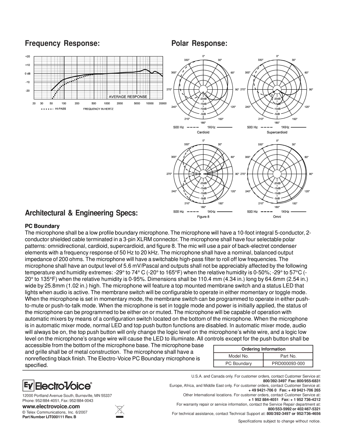
Frequency Response: | Polar Response: |
| | | | | | | | | | | | | | | | | | | | | | | | | | | | | | | | | | | | | | | | | | | | | | | | | | | | | | | | | | | | | | | | | | | | | | | |
| | | | | | | | | | | | | | | | | | | | | | | | | | | | | | | | | | | | | | | | | | | | | | | | | | | | | | | | | | | | | | | | | | | | | | | |
Architectural & Engineering Specs:
PC Boundary
The microphone shall be a low profile boundary microphone. The microphone will have a 10-foot integral 5-conductor, 2- conductor shielded cable terminated in a 3-pin XLRM connector. The microphone shall have four selectable polar patterns: omnidirectional, cardioid, supercardioid, and figure 8. The mic will use a pair of back-electret condenser elements with a frequency response of 50 Hz to 20 kHz. The microphone shall have a nominal, balanced output impedance of 200 ohms. The microphone will have a switchable high-pass filter to roll off low frequencies. The microphone shall have an output level of 5.6 mV/Pascal and outputs shall not be appreciably affected by the following temperature and humidity extremes: -29° to 74° C (-20° to 165°F) when the relative humidity is 0-50%; -29° to 57°C (- 20° to 135°F) when the relative humidity is 0-95%. Dimensions shall be 110.4 mm (4.34 in.) long by 64.6mm (2.54 in.) wide by 25.8mm (1.02 in.) high. The microphone will feature a top mounted membrane switch and a status LED that lights when audio is active. The membrane switch will be configurable to operate in either momentary or toggle mode. When the microphone is set in momentary mode, the membrane switch can be programmed to operate in either push- to-mute or push-to-talk mode. When the microphone is set in toggle mode and power is initially applied, the status of the microphone can be programmed to be either on or muted. The microphone will be capable of operation with automatic mixers by means of a configuration switch located on the bottom of the microphone. When the microphone is in automatic mixer mode, normal LED and top push button functions are disabled. In automatic mixer mode, audio will always be on, the top push button will only change the logic level on the microphone’s white wire, and a logic low
| | level on the microphone’s orange wire will cause the LED to illuminate. All controls except for the push button shall be |
| | accessible from the bottom of the microphone base. The microphone base | | | |
| | Ordering Information | |
| | and grille shall be of metal construction. The microphone shall have a | |
| | | | |
| | Model No. | Part No. | |
| | nonreflecting black finish. The Electro-Voice PC Boundary microphone is | |
| | | | |
| | PC Boundary | PRD000093-000 | |
| | specified. | |
| | | | | | | | | | |
| | | | | | | | | | |
| | | | | | | | | | |
| | | | | | | | | | |
12000 Portland Avenue South, Burnsville, MN 55337
Phone: 952/884-4051, Fax: 952/884-0043
www.electrovoice.com
© Telex Communications, Inc. 6/2007
Part Number LIT000111 Rev. B