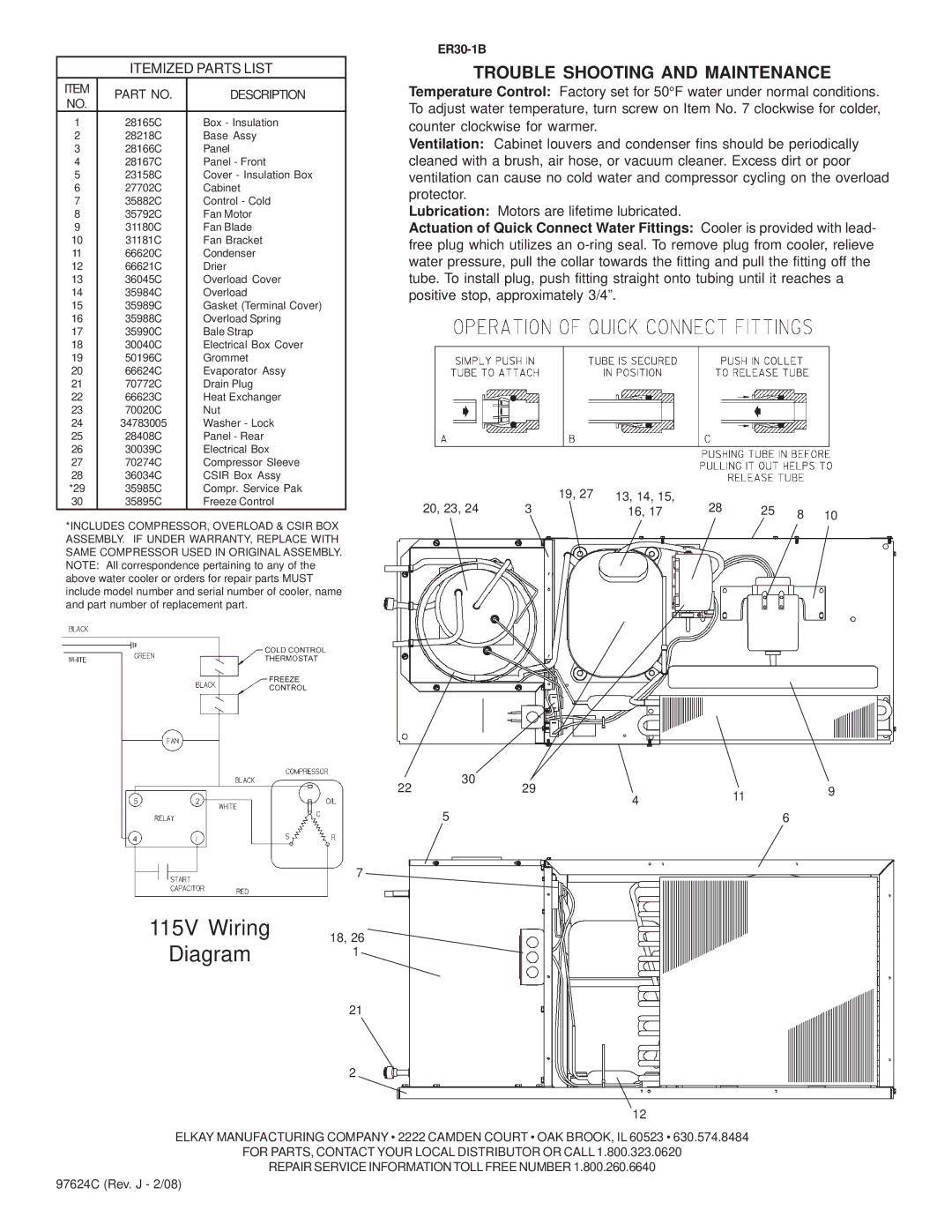
ER30-1B specifications
The Elkay ER30-1B is a state-of-the-art water station that reflects a perfect blend of functionality and modern design. Ideal for schools, parks, and public facilities, this sleek and user-friendly unit promotes hydration while emphasizing sustainability and health.One of the standout features of the Elkay ER30-1B is its innovative filtration system. The unit comes equipped with a built-in filtered water dispenser that provides clean, fresh drinking water, ensuring that users can stay hydrated without needing single-use plastic bottles. This not only reduces waste but also encourages an environmentally conscious lifestyle.
The Elkay ER30-1B employs advanced sensor technology, allowing for touchless operation. Users can enjoy a hands-free experience, which is particularly beneficial in high-traffic areas where sanitation is a priority. The motion-sensor activation enhances convenience, as it enables quick and easy access to refreshing water without needing to touch surfaces. This feature is especially appealing in today's health-conscious environment.
Another notable characteristic is the unit’s durable construction. The ER30-1B is made of high-quality stainless steel, which ensures longevity, resistance to corrosion, and ease of cleaning. Its robust design is built to withstand heavy usage, making it an ideal choice for busy locations. The sleek aesthetic of the unit fits seamlessly with various architectural styles, enhancing the visual appeal of any location.
In addition, the Elkay ER30-1B is designed with efficiency in mind. It features a capacity of providing an ample amount of water, with the capability to accommodate multiple users at once. The user-friendly design includes a convenient bottle filling station that allows users to refill their reusable water bottles quickly.
Moreover, the Elkay ER30-1B includes an LED filter status indicator, which alerts users when it’s time to replace the filter. This ensures that users always have access to clean water, maintaining the highest standards of hydration quality.
Overall, the Elkay ER30-1B is an exemplary solution for modern water accessibility. With its combination of eco-friendliness, user-friendly technology, and robust design, it stands out as a must-have in any facility focused on promoting health and sustainability. By providing easy access to filtered water, it not only serves the hydration needs of users but also plays a crucial role in reducing environmental impact.

