1F82-261 specifications
The Emerson 1F82-261 and 1F89-211 are advanced programmable thermostats designed to enhance home comfort, energy efficiency, and convenience. These devices represent the latest in heating and cooling management technology, aiming to provide homeowners with intuitive control over their indoor climate.One of the primary features of the Emerson 1F82-261 is its user-friendly interface. The large backlit display is easy to read, even in low light conditions. Users can quickly adjust settings, view the current temperature, and access programming options without hassle. Both models come equipped with a touch screen feature, allowing for simple navigation through menus and settings compared to older dial models.
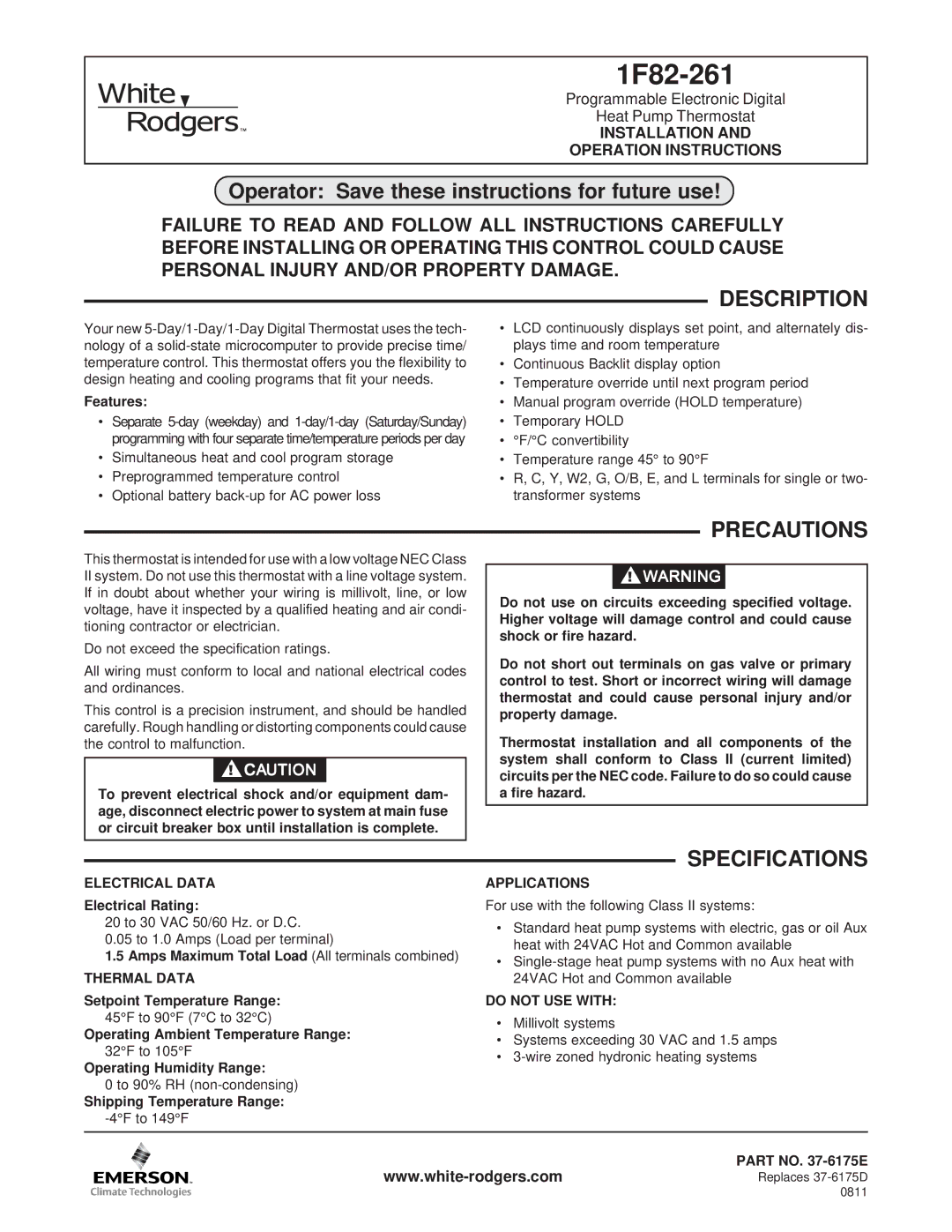
The 1F82-261 model supports up to 2 heating and 1 cooling stages, making it suitable for multi-stage HVAC systems. It is ideal for those looking to optimize home heating or cooling while ensuring comfort. On the other hand, the 1F89-211 is designed for even greater versatility, offering compatibility with up to 2 stages of heating and 2 stages of cooling. This makes it an excellent choice for larger or more complex heating and cooling systems.
A highlight of both thermostats is their programmability. Users can set schedules for different days of the week through a simple programming interface. This feature allows homeowners to reduce energy consumption by adjusting the temperature based on occupancy patterns, ensuring that energy is not wasted while the house is empty.
Another significant technology incorporated into these models is the Smart Response feature. This intelligent technology enables the thermostat to learn the household's heating and cooling patterns, making adjustments ahead of time to reach the desired temperature right when it is needed. This not only enhances comfort but also contributes to energy savings.
Further emphasizing energy efficiency, the Emerson thermostats include an auto-changeover feature for seamless transition between heating and cooling modes, depending on the current temperature. This technology ensures that your home maintains a consistent, comfortable climate throughout varying conditions.
Both models also support Wi-Fi connectivity, allowing for remote access and control via smartphone apps. This feature provides the convenience of monitoring and adjusting home temperatures from anywhere, enabling homeowners to arrive at a perfectly comfortable home after a long day.
In summary, the Emerson 1F82-261 and 1F89-211 combine modern design with intelligent features, making them ideal choices for anyone looking to enhance their home’s comfort and energy efficiency. With easy-to-use interfaces, advanced programmability, and smart technologies, these thermostats provide reliable solutions for efficient climate control.