Serial Communications
Serial communications permits large amounts of information to be processed over a few wires. In the serial communications systems used by ASCO, each individual device in the system
Sending and receiving requests and commands is done over the same pair of twisted wires linked in a network fashion from one device to another to form the communication link, or highway. This physical configuration comprises a network in which only the addressed device is permitted to go on line and respond to an inquiry. With this serial communications system, a minimum number of wires can be used to link the elements together. Without serial communications, it would take considerably more wires to accomplish the same thing.
INSTALLATION
The ATS Annunciator has been tested and is ready to use. Installation simply requires mounting, connecting power and communication wiring, and setting DIP switches. When unpacking the unit, locate the loose parts which are supplied in a separate kit. The kits contain the following parts:
Master Kit 401091 | Slave Kit 401092 |
label holder labels | label holder labels, |
& 2 resistors | 2 resistors, & ribbon cable |
The Master ATS Annunciator can be readily identified by the front mounted key switch (to prevent unauthorized operation). You will find the key taped inside the back panel. Up to two Slave ATS Annunciators can be mounted directly above or below the Master. All three ATS Annun- ciators are then interconnected by means of ribbon cables. All external wiring for power and serial communication line connects to the Master ATS Annunciator. Observe the requirements of the National Electrical Code (especially Articles 725 and 800) and any local codes when interwiring.
Mounting
An Outline and Installation drawing (JS 387797) is included in the back of this manual. The
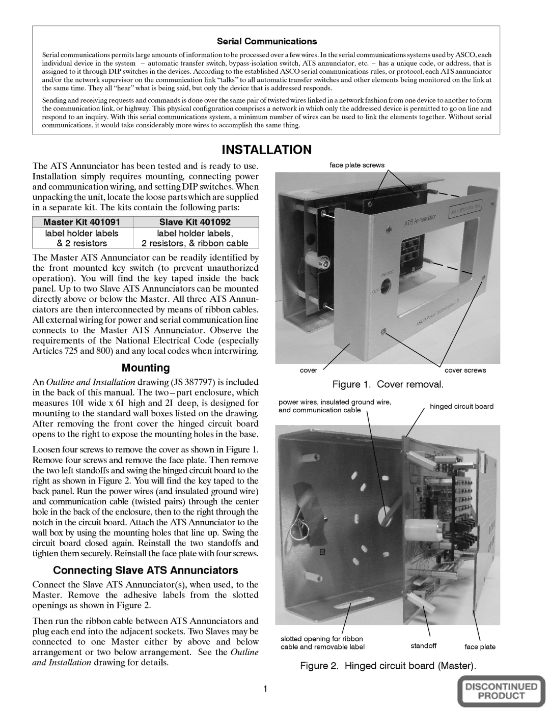
Loosen four screws to remove the cover as shown in Figure 1. Remove four screws and remove the face plate. Then remove the two left standoffs and swing the hinged circuit board to the right as shown in Figure 2. You will find the key taped to the back panel. Run the power wires (and insulated ground wire) and communication cable (twisted pairs) through the center hole in the back of the enclosure, then to the right through the notch in the circuit board. Attach the ATS Annunciator to the wall box by using the mounting holes that line up. Swing the circuit board closed again. Reinstall the two standoffs and tighten them securely. Reinstall the face plate with four screws.
Connecting Slave ATS Annunciators
Connect the Slave ATS Annunciator(s), when used, to the Master. Remove the adhesive labels from the slotted openings as shown in Figure 2.
Then run the ribbon cable between ATS Annunciators and plug each end into the adjacent sockets. Two Slaves may be connected to one Master either by above and below arrangement or two below arrangement. See the Outline and Installation drawing for details.
face plate screws
cover | cover screws |
Figure 1. | Cover removal. |
power wires, insulated ground wire, | hinged circuit board | |
and communication cable | ||
|
slotted opening for ribbon | standoff |
|
cable and removable label | face plate |
Figure 2. Hinged circuit board (Master).
1