
CF742PFWW 01, CF742PFSCB 01 specifications
The Emerson CF742PFSCB 01 and CF742PFWW 01 ceiling fans are exceptional additions to any home, combining modern design with advanced technology for optimal performance and aesthetic appeal. Both models showcase Emerson’s commitment to quality and functionality, ensuring they meet the diverse needs of consumers seeking efficient air circulation.One of the standout features of the CF742PFSCB 01 and CF742PFWW 01 is their sleek and stylish design, available in various finishes that can seamlessly blend into any décor. The CF742PFSCB 01 boasts a sophisticated brushed steel finish, while the CF742PFWW 01 offers a more classic white appearance. This variety makes it easy for purchasers to select a fan that complements their interior design.
Both models are equipped with powerful and energy-efficient motors that ensure quiet operation, which is essential for maintaining a peaceful environment, especially in bedrooms and living areas. The fans are designed to circulate air effectively, providing a refreshing breeze during hot summer days, while their reverse function allows for warm air redistribution during colder months. This versatility enhances year-round comfort, making them a practical choice for any climate.
The Emerson CF742PFSCB 01 and CF742PFWW 01 also feature five blades crafted for maximum airflow while minimizing energy consumption. This efficiency is part of Emerson’s commitment to sustainability, allowing users to enjoy the benefits of ceiling fans without significantly impacting their energy bills. The fans support various speeds, allowing users to customize airflow according to personal preference and environmental conditions.
Moreover, these ceiling fans come with an easy-to-use remote control, enabling effortless adjustments from anywhere in the room. This convenience is a significant benefit for those looking to optimize their comfort without having to get up frequently.
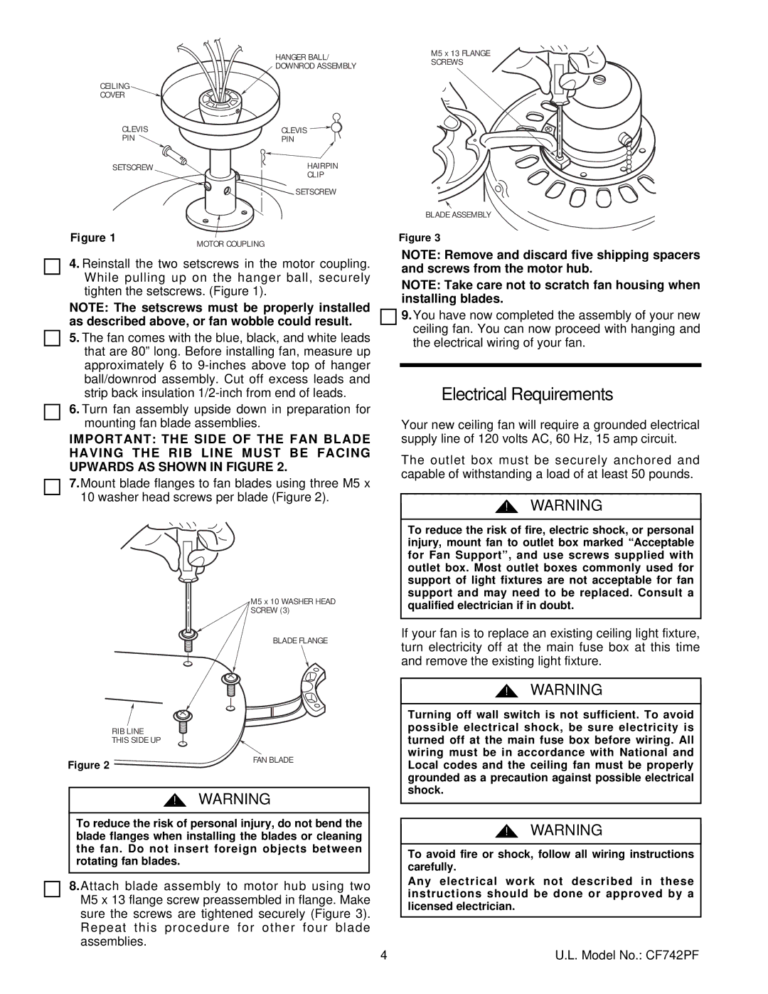
Installation of the CF742PFSCB 01 and CF742PFWW 01 is straightforward, with comprehensive instructions and compatible mounting options included, ensuring users can enjoy their new ceiling fan without unnecessary hassle.
In conclusion, the Emerson CF742PFSCB 01 and CF742PFWW 01 ceiling fans are designed to enhance both the comfort and aesthetic appeal of living spaces. With their stylish designs, energy-efficient technology, and user-friendly features, they are ideal for homeowners looking to elevate their environments while ensuring effective air circulation throughout the year.