Configuring the LP21000 as a Network Adapter
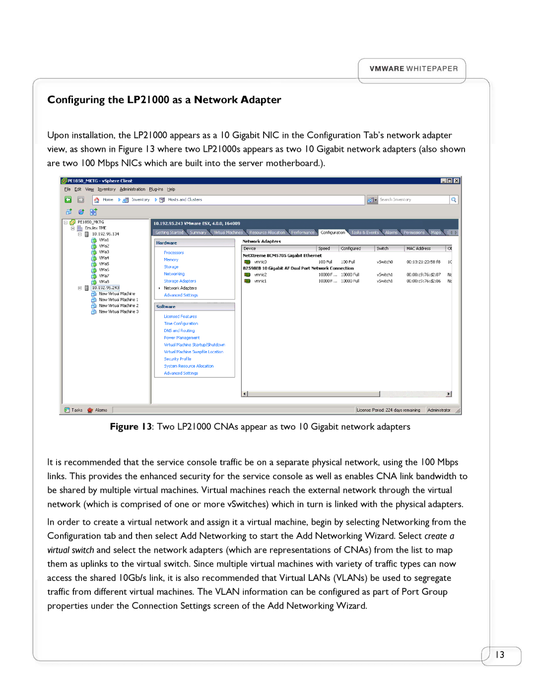
Upon installation, the LP21000 appears as a 10 Gigabit NIC in the Configuration Tab’s network adapter view, as shown in Figure 13 where two LP21000s appears as two 10 Gigabit network adapters (also shown are two 100 Mbps NICs which are built into the server motherboard.).
Figure 13: Two LP21000 CNAs appear as two 10 Gigabit network adapters
It is recommended that the service console traffic be on a separate physical network, using the 100 Mbps links. This provides the enhanced security for the service console as well as enables CNA link bandwidth to be shared by multiple virtual machines. Virtual machines reach the external network through the virtual network (which is comprised of one or more vSwitches) which in turn is linked with the physical adapters.
In order to create a virtual network and assign it a virtual machine, begin by selecting Networking from the Configuration tab and then select Add Networking to start the Add Networking Wizard. Select create a virtual switch and select the network adapters (which are representations of CNAs) from the list to map them as uplinks to the virtual switch. Since multiple virtual machines with variety of traffic types can now access the shared 10Gb/s link, it is also recommended that Virtual LANs (VLANs) be used to segregate traffic from different virtual machines. The VLAN information can be configured as part of Port Group properties under the Connection Settings screen of the Add Networking Wizard.
13