
RS232-RS485 specifications
Equinox Systems RS232-RS485 is a crucial device in the realm of industrial communication, facilitating the seamless transition between RS232 and RS485 protocols. This converter is essential for applications where devices equipped with RS232 need to communicate over longer distances or in noisy environments where RS485 excels.One of the main features of the Equinox Systems RS232-RS485 converter is its ability to support long cable runs. RS232 typically allows communication over short distances, typically up to 50 feet, while RS485 can extend this reach to over 4000 feet. This flexibility is vital in large industrial settings, where devices may be located far apart.
Another significant feature is its robust data transmission capabilities. RS485 is well-known for its differential signaling, which enhances noise immunity and allows for reliable communication in electrically noisy environments. The converter supports multi-drop configurations, enabling multiple devices to be connected on the same network without signal degradation.
The technology employed in the Equinox Systems RS232-RS485 converter includes advanced signal processing, which ensures high data integrity and reduces error rates during transmission. It typically operates at baud rates up to 115200 bps, making it suitable for various data-intensive applications.
In terms of compatibility, this converter is designed to work seamlessly with various devices, including PLCs, industrial sensors, and computers. Its ease of use is enhanced by features like auto-sensing, which automatically adjusts to the different communication settings of connected devices.
The design also prioritizes durability, featuring robust enclosures that protect against dust and moisture. This makes it suitable for operations in challenging environments, such as manufacturing plants and outdoor installations.
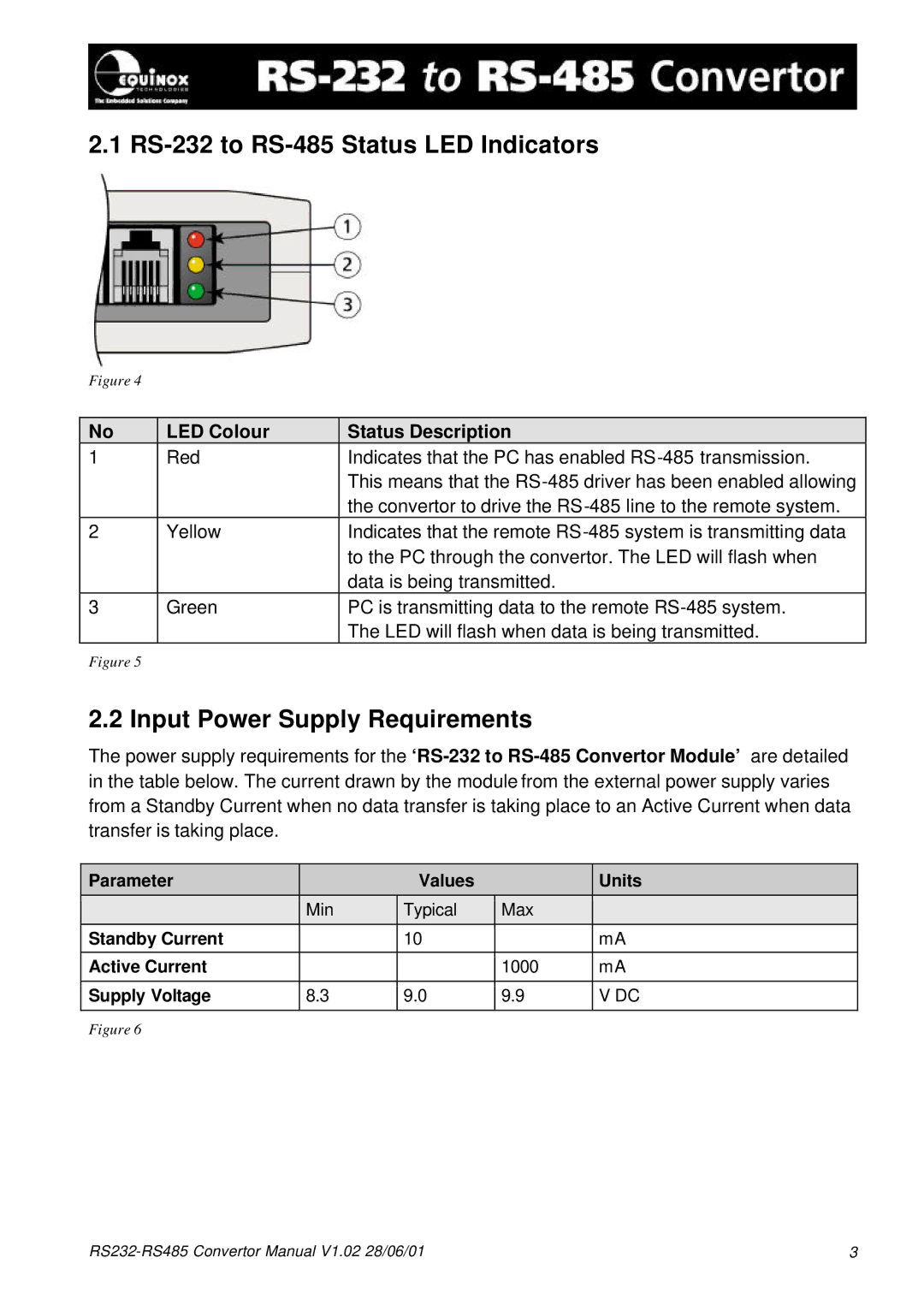
Additionally, the Equinox Systems RS232-RS485 converter is often equipped with LED indicators that provide real-time feedback on data transmission status, aiding in diagnostics and maintenance.
In summary, the Equinox Systems RS232-RS485 converter stands out for its versatility, reliability, and ease of integration into existing systems. Whether in industrial automation, building management, or extensive network systems, its ability to facilitate effective communication between devices using different protocols makes it an invaluable asset in modern communication solutions.