LS102
Wireless Switch
Installation
Guide
Supported Models and Requirements
Europe: EFLS102/N1W UK: EFLS102/N1W
This device requires a neutral AC connection.
This device requires a
Specifications and Supported Fixtures
This switch operates independently or as a device you can control with your Escient® system. It installs in a standard wall box using typical wiring standards and communicates to the Escient system using a wireless connection. The specifications and supported fixtures are described below.
Installation Instructions
1 Ensure that the location and intended use meet the following criteria:
•The range and performance of the wireless control system is highly dependent on the following: (1) distance between devices; (2) layout of the home; (3) walls separating devices; and (4) electrical equipment located near devices.
•DO NOT exceed maximum load rating of switch (which is 1000 Volt for a single unit).
WARNING! Disconnect power before installing or servicing the device.
2 Switch off and isolate the mains power at the main consumer unit or fuse box before starting any installation or maintenance work.
3 Prepare the wall box and wires:
•Ensure a
•Strip each wire’s insulation back 7.3 mm (0.287 in.) from the wire end (as shown).
Figure 1. Strip Wire Insulation
WARNING! This is a Class 1 product and must be Earthed.
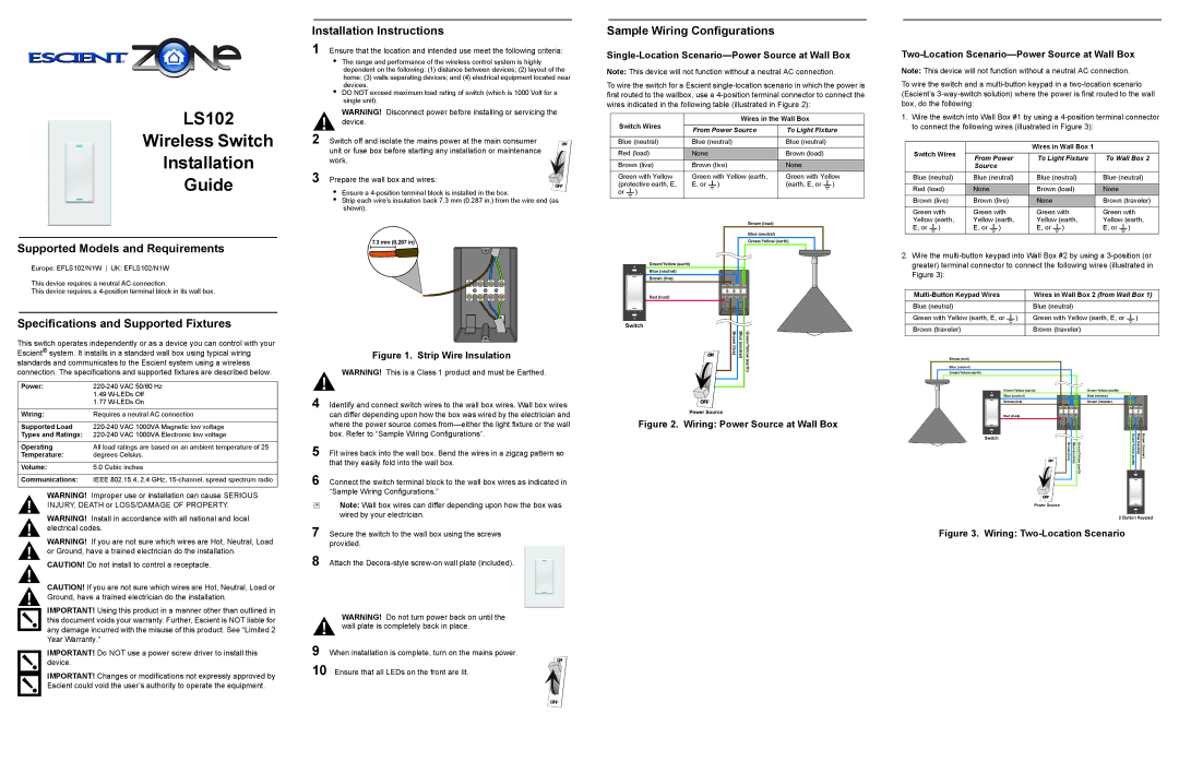
Sample Wiring Configurations
Single-Location Scenario—Power Source at Wall Box
Note: This device will not function without a neutral AC connection.
To wire the switch for a Escient
Switch Wires | Wires in the Wall Box | ||
|
| ||
From Power Source | To Light Fixture | ||
| |||
|
|
| |
Blue (neutral) | Blue (neutral) | Blue (neutral) | |
|
|
| |
Red (load) | None | Brown (load) | |
|
|
| |
Brown (live) | Brown (live) | None | |
Green with Yellow | Green with Yellow (earth, | Green with Yellow | |
(protective earth, E, | E, or ) | (earth, E, or ) | |
or ) |
|
| |
Two-Location Scenario—Power Source at Wall Box
Note: This device will not function without a neutral AC connection.
To wire the switch and a
1.Wire the switch into Wall Box #1 by using a
Switch Wires |
| Wires in Wall Box 1 |
| |
|
|
| ||
From Power | To Light Fixture | To Wall Box 2 | ||
| ||||
| Source |
|
| |
|
|
|
| |
Blue (neutral) | Blue (neutral) | Blue (neutral) | Blue (neutral) | |
|
|
|
| |
Red (load) | None | Brown (load) | None | |
Brown (live) | Brown (live) | None | Brown (traveler) | |
Green with | Green with | Green with | Green with | |
Yellow (earth, | Yellow (earth, | Yellow (earth, | Yellow (earth, | |
E, or ) | E, or ) | E, or ) | E, or ) | |
|
|
|
|
2.Wire the
Wires in Wall Box 2 (from Wall Box 1) | |
|
|
Blue (neutral) | Blue (neutral) |
|
|
Green with Yellow (earth, E, or ) | Green with Yellow (earth, E, or ) |
|
|
Brown (traveler) | Brown (traveler) |
|
|
Power: | VAC 50/60 Hz | |
| 1.49 | |
| 1.77 | |
|
| |
Wiring: | Requires a neutral AC connection | |
|
|
|
Supported Load | VAC 1000VA Magnetic low voltage | |
Types and Ratings: | VAC 1000VA Electronic low voltage | |
|
| |
Operating | All load ratings are based on an ambient temperature of 25 | |
Temperature: | degrees Celsius. | |
|
| |
Volume: | 5.0 Cubic inches | |
|
| |
Communications: | IEEE 802.15.4, 2.4 GHz, | |
|
|
|
WARNING! Improper use or installation can cause SERIOUS INJURY, DEATH or LOSS/DAMAGE OF PROPERTY.
WARNING! Install in accordance with all national and local electrical codes.
WARNING! If you are not sure which wires are Hot, Neutral, Load or Ground, have a trained electrician do the installation.
CAUTION! Do not install to control a receptacle.
CAUTION! If you are not sure which wires are Hot, Neutral, Load or Ground, have a trained electrician do the installation.
IMPORTANT! Using this product in a manner other than outlined in this document voids your warranty. Further, Escient is NOT liable for any damage incurred with the misuse of this product. See “Limited 2 Year Warranty.”
IMPORTANT! Do NOT use a power screw driver to install this device.
IMPORTANT! Changes or modifications not expressly approved by Escient could void the user’s authority to operate the equipment.
4 Identify and connect switch wires to the wall box wires. Wall box wires can differ depending upon how the box was wired by the electrician and where the power source comes
5 Fit wires back into the wall box. Bend the wires in a zigzag pattern so that they easily fold into the wall box.
6 Connect the switch terminal block to the wall box wires as indicated in “Sample Wiring Configurations.”
Note: Wall box wires can differ depending upon how the box was wired by your electrician.
7 Secure the switch to the wall box using the screws provided.
8 Attach the
WARNING! Do not turn power back on until the wall plate is completely back in place.
9 When installation is complete, turn on the mains power. 10 Ensure that all LEDs on the front are lit.