Easy 4 Step Assembly
To view our “How to Assemble” demo, visit www.eureka.com/airspeed/assembly
| STEP |
|
| 1 |
|
| Fig. 1 | Alternate View |
B |
| |
| A | B |
|
| |
|
| A |
Fig. 2 |
|
|
| B |
|
| A |
|
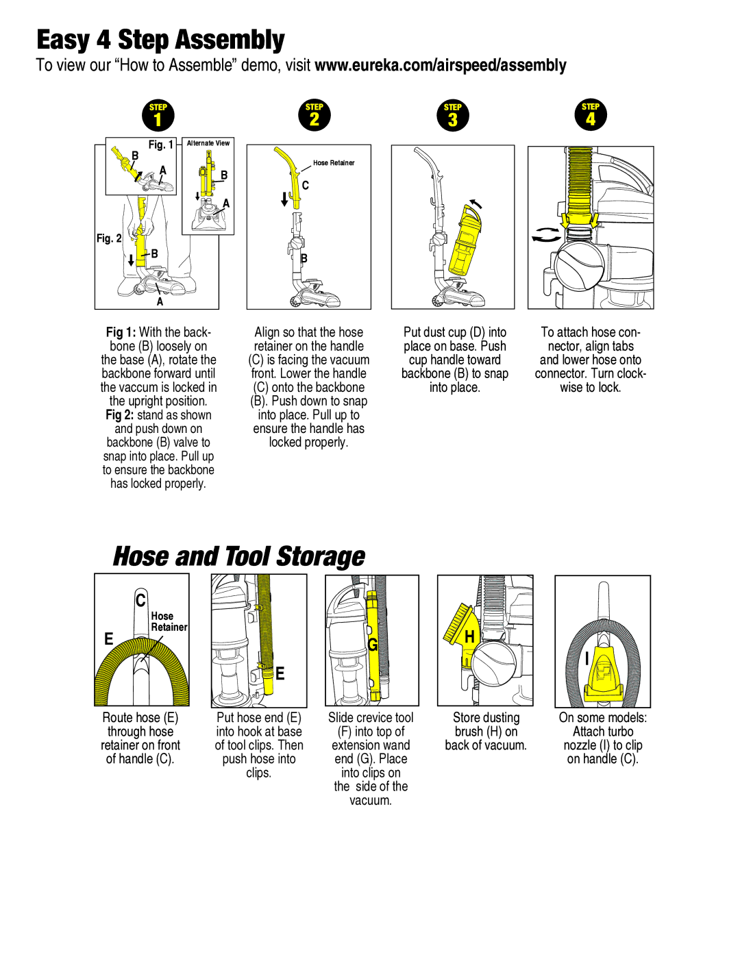
Fig 1: With the back- bone (B) loosely on the base (A), rotate the backbone forward until the vaccum is locked in the upright position. Fig 2: stand as shown and push down on backbone (B) valve to snap into place. Pull up to ensure the backbone has locked properly.
STEP | STEP | STEP |
2 | 3 | 4 |
Hose Retainer
C
B
Align so that the hose | Put dust cup (D) into | To attach hose con- |
retainer on the handle | place on base. Push | nector, align tabs |
(C) is facing the vacuum | cup handle toward | and lower hose onto |
front. Lower the handle | backbone (B) to snap | connector. Turn clock- |
(C) onto the backbone | into place. | wise to lock. |
(B). Push down to snap |
|
|
into place. Pull up to |
|
|
ensure the handle has |
|
|
locked properly. |
|
|
Hose and Tool Storage
C
E
Hose Retainer
![]() E
E
G![]()
Route hose (E)
through hose
retainer on front
of handle (C).
Put hose end (E) into hook at base of tool clips. Then push hose into clips.
Slide crevice tool
(F)into top of extension wand end (G). Place
into clips on
the side of the
vacuum.
Store dusting brush (H) on back of vacuum.
On some models:
Attach turbo
nozzle (I) to clip on handle (C).