e-7050, 630i, 7150, e-610i, 112-CK-NF70 specifications
The EVGA e-7050, 7150, 630i, e-610i, and 112-CK-NF70 motherboards represent a diverse lineup tailored for various computing needs, particularly within the realm of budget-conscious consumers and gaming enthusiasts. Each model is designed with a focus on reliability, expandability, and advanced integrated technologies that cater to the evolving demands of modern computing.The EVGA e-7050 and 7150 motherboards are built on the NVIDIA GeForce 7050 chipset, offering integrated graphics that deliver decent performance for casual gaming and multimedia applications. With support for up to 8GB of DDR2 memory, these boards provide ample bandwidth for multitasking and basic gaming. They feature PCI Express x16 slots, facilitating the addition of discrete graphics cards for users seeking higher performance levels. Their compact design ensures compatibility with a variety of cases, making them ideal for small form-factor builds.
The EVGA 630i motherboard takes a step further by utilizing the NVIDIA GeForce 630i chipset, known for its energy-efficient design while still providing solid performance. This model includes integrated graphics with support for DirectX 10, enhancing the visual experience for everyday tasks and light gaming. The 630i supports a wide range of Intel processors, including Core 2 Duo and Pentium D, providing flexibility in CPU choices for users. With dual-channel DDR2 memory capabilities, it ensures effective handling of various applications.
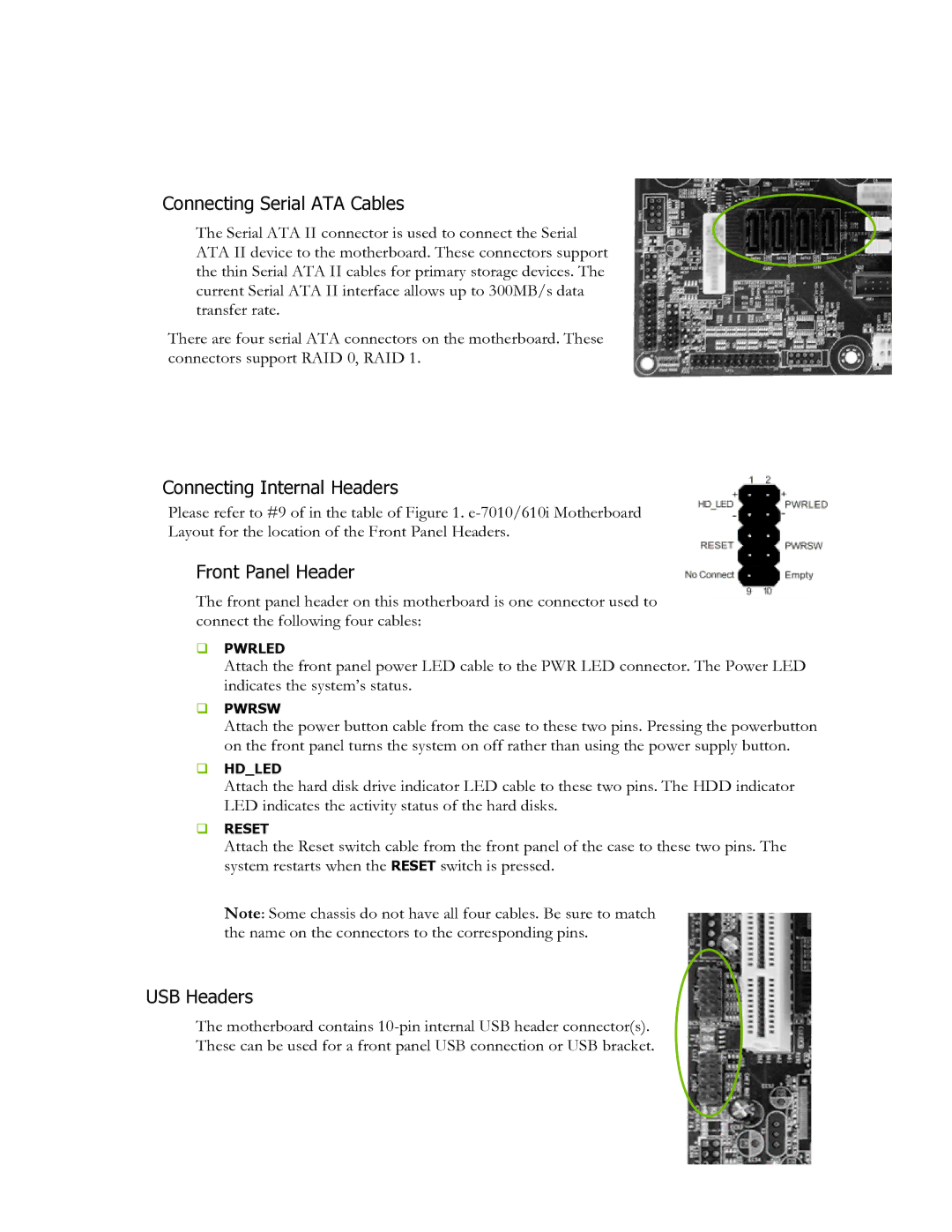
The EVGA e-610i is designed with basic computing in mind, suitable for home and office use. It integrates reliable components that offer stability and performance for tasks such as office applications, internet browsing, and light media consumption. Despite its more simplified approach, the e-610i does not compromise on essential features, including multiple USB ports and SATA connectors, ensuring user-friendly connectivity.
Lastly, the EVGA 112-CK-NF70 motherboard is notable for its advanced feature set. Built around the NVIDIA nForce 570 chipset, it is aimed at gamers and performance-driven users. It supports dual graphics setups for enhanced rendering capabilities and offers more robust memory support with higher frequencies. This model is ideal for users looking to create high-performance gaming rigs or workstations.
Overall, the EVGA e-7050, 7150, 630i, e-610i, and 112-CK-NF70 motherboards exemplify a balance of performance, expandability, and value. Each one is designed to meet specific user needs, whether for everyday computing, light gaming, or high-performance tasks, showcasing EVGA's commitment to quality and innovation in the motherboard market.

