D/2 DA4 DVI specifications
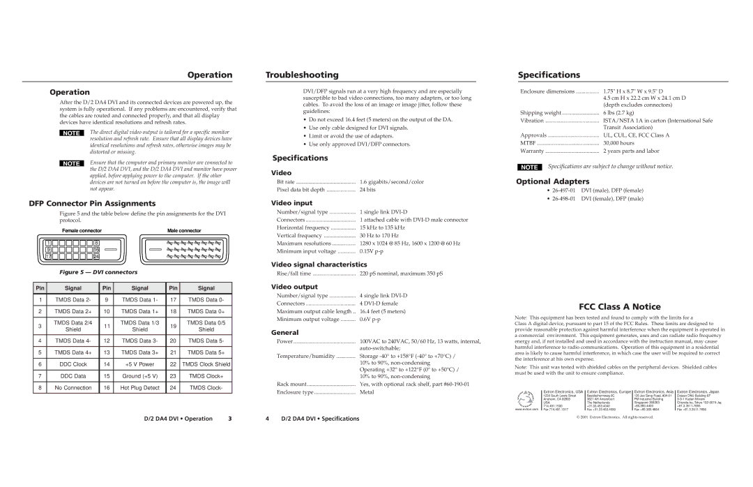
Extron Electronics has long been a key player in the realm of professional AV solutions, and their D/2 DA4 DVI distribution amplifier exemplifies the company’s commitment to cutting-edge technology and performance. Designed for use in a variety of applications, including presentation systems, classrooms, and corporate environments, the D/2 DA4 DVI serves as an essential tool for distributing DVI-D signals to multiple displays without loss of quality.One of the standout features of the D/2 DA4 DVI is its ability to support high-resolution video signals up to 1920x1200 at 60Hz. This capability ensures that users can enjoy stunning visuals with clarity and detail, making it ideal for environments that demand high-quality image reproduction. The unit can distribute a single DVI-D input to four identical DVI-D outputs, which is crucial for applications requiring multiple display screens.
Another significant characteristic of the D/2 DA4 DVI is its advanced reclocking technology. This feature rejuvenates the digital signal, compensating for any signal degradation that may occur over long cable runs. As a result, users can expect consistent performance, even in complex setups involving long distances between the source and the displays.
The compact, rack-mountable design of the D/2 DA4 DVI adds versatility to its application. The unit integrates seamlessly into existing AV racks while occupying minimal space, which is particularly advantageous for installations where space is at a premium. With balanced audio capabilities, the D/2 DA4 DVI also accommodates simultaneous audio distribution, supporting a more comprehensive AV experience.
Extron’s Global Control functionality further enhances the D/2 DA4 DVI, allowing users to integrate control features smoothly into their AV architecture. This capability promotes centralized management of multiple devices, simplifying the operation and improving efficiency during presentations or lectures.
In addition to its primary features, the D/2 DA4 DVI also incorporates EDID management, ensuring optimal communication between source and sink devices. This management capability helps prevent resolution mismatches, ultimately resulting in improved reliability and user satisfaction.
Overall, the Extron D/2 DA4 DVI distribution amplifier stands out as a sophisticated solution for professional applications requiring high-quality video distribution. Its combination of advanced technology, robust features, and user-friendly design make it an invaluable asset for anyone looking to enhance their AV deployment. Whether for corporate presentations, educational purposes, or rental and staging scenarios, the D/2 DA4 DVI ensures that users can achieve exceptional visual performance without compromise.

