
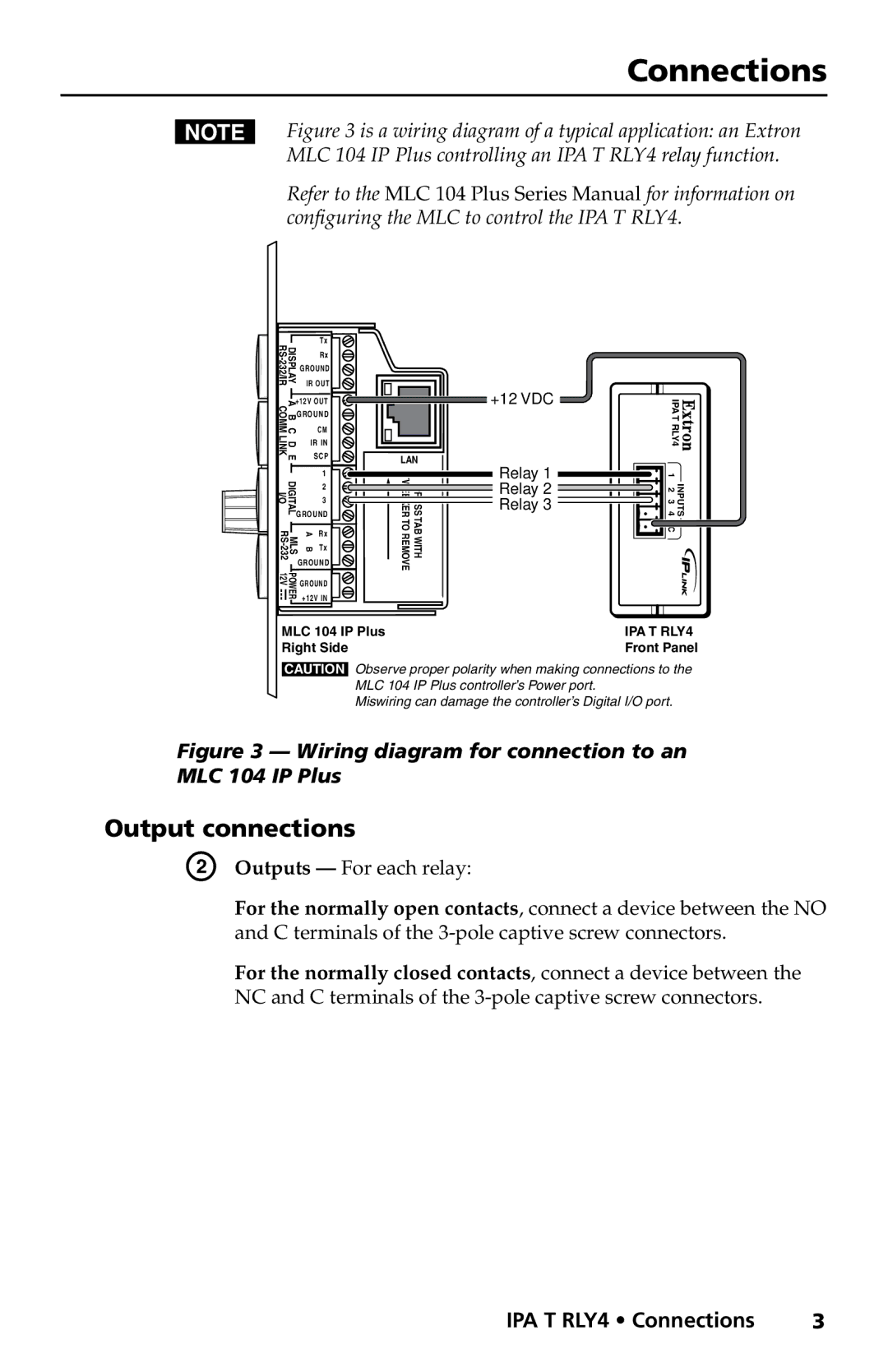
IPA T RLY4 specifications
The Extron Electronics IPA T RLY4 is a state-of-the-art audio relay switcher designed for sophisticated AV system control. It serves as an essential component for simplifying the integration of audio and control signals in various professional environments such as corporate, educational, and entertainment settings. Equipped with four relay outputs, the IPA T RLY4 allows for easy control over audio routing to different devices, enabling users to create dynamic and responsive audio experiences.One of the standout features of the IPA T RLY4 is its ability to facilitate seamless audio switching. It incorporates relay technology that ensures minimal audio signal degradation, allowing users to maintain audio quality even when switching between multiple sources. This is particularly beneficial in critical applications where sound fidelity is paramount.
The IPA T RLY4 also includes advanced control options, encompassing both manual and automated functionalities. Users can integrate the device with other Extron control systems or third-party controllers for comprehensive AV management. This flexibility empowers users to create customized control schemes that enhance operational efficiency and user experience. Additionally, the IPA T RLY4 supports Extron’s global configuration and programming software, which aids in rapid installation and setup.
In terms of connectivity, the IPA T RLY4 is equipped with multiple input/output options, including balanced and unbalanced audio inputs. This diverse set of connectivity options makes it compatible with a wide range of audio sources, such as mixers, microphones, and amplifiers. Furthermore, the compact form factor of the device allows for easy installation in various environments, including equipment racks or standalone setups.
The IPA T RLY4 also features comprehensive signal indication capabilities, with LED indicators that provide real-time feedback on relay status and operational health. This diagnostic feature enhances troubleshooting efficiency, allowing users to quickly identify and rectify any issues that may arise.
Overall, the Extron IPA T RLY4 is an integral component for any audio system, combining robust audio switching, advanced control features, and superior signal integrity. Its design and functionalities cater to the needs of professionals seeking a reliable and efficient solution for managing audio distribution. With the IPA T RLY4, Extron continues to set benchmarks in the field of AV technology, ensuring that users receive the best performance and quality in their audio applications.