Installation and Operation
Introduction
The KP 6 is designed to control MSW 4 Series, SW AV Series (4 and 6 input models only), SW VGA/Ars Series, and SW RGBHV/ A Series switchers, or other Extron products with contact closure ports or ports labeled as “Remote.”
The KP 6 is a contact closure remote for selecting the switcher’s input. When a number key is pressed, the wire associated with that input is momentarily shorted to ground, making the switcher switch to that input.
The KP 6 can control up to 6 inputs and requires no power.
Installation
Installation with a 9-pin D-sub connector
Many switchers, such as the SW6 VGA Ars Switcher, come equipped with a
1. | Power down the switcher. | |||
2. | Connect the KP 6 adapter’s | |||
| connector on the switcher’s rear panel. | |||
3. | Position the KP 6 Keypad for the most convenient operation. | |||
4. | Power up the switcher. |
| ||
|
|
|
| 25 foot |
|
|
|
| cable |
| INPUTS | REMOTE | SW6VGAArsArs | |
| 1 | 3 | 5 |
|
|
|
|
| OUTPUT | OUTPUT | |
2 | 4 | 6 |
| L | R | |
SW6 VGA Ars Switcher
KP 6 Keypad
Remote Control
Figure 1 — Typical KP 6 application (with 9-pin D- sub connector)
|
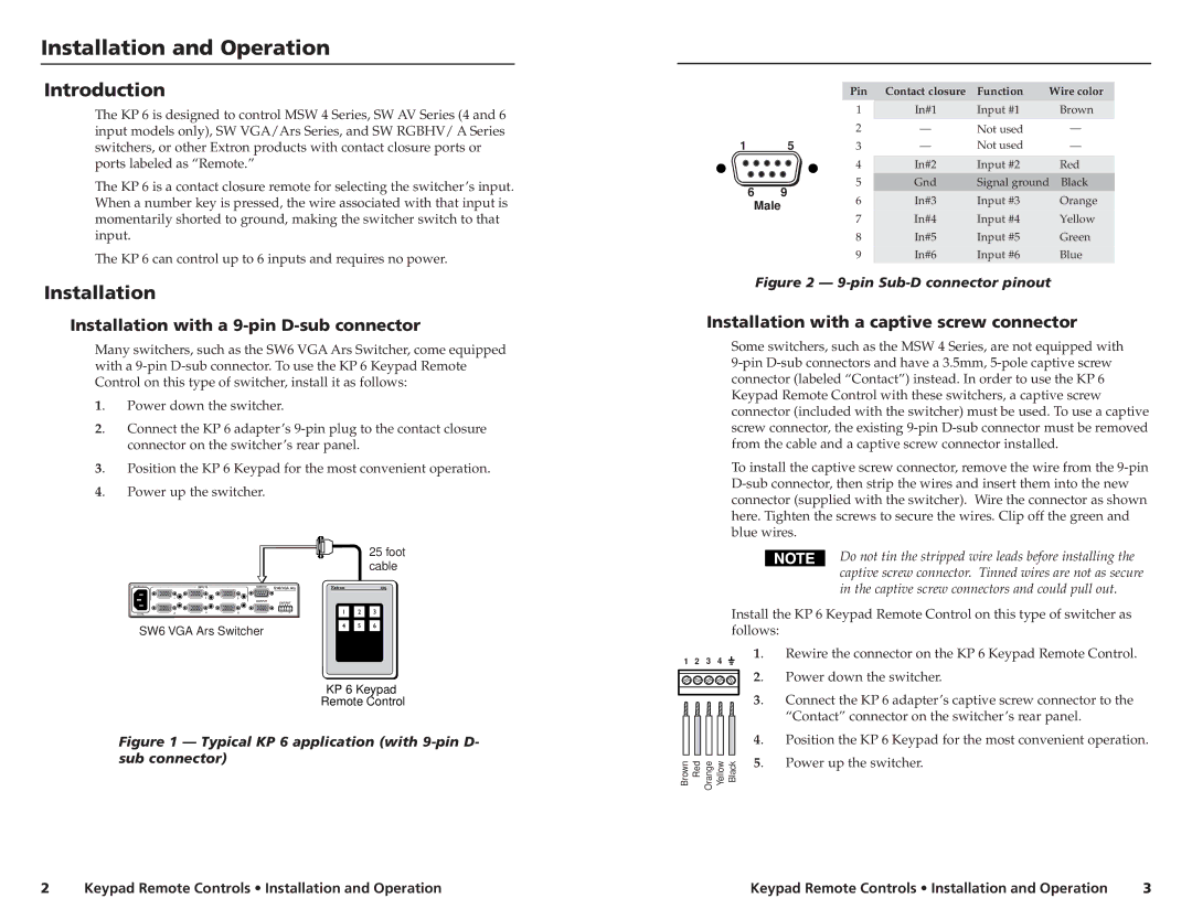
| Pin | Contact closure | Function | Wire color | |
|
| 1 | In#1 | Input #1 | Brown | |
|
| 2 | — | Not used | — | |
1 | 5 | 3 | — | Not used | — | |
|
| 4 | In#2 | Input #2 | Red | |
6 | 9 | 5 | Gnd | Signal ground Black | ||
6 | In#3 | Input #3 | Orange | |||
Male | ||||||
7 | In#4 | Input #4 | Yellow | |||
|
| |||||
|
| 8 | In#5 | Input #5 | Green | |
|
| 9 | In#6 | Input #6 | Blue | |
Figure 2 — 9-pin Sub-D connector pinout
Installation with a captive screw connector
Some switchers, such as the MSW 4 Series, are not equipped with
To install the captive screw connector, remove the wire from the
Do not tin the stripped wire leads before installing the captive screw connector. Tinned wires are not as secure in the captive screw connectors and could pull out.
Install the KP 6 Keypad Remote Control on this type of switcher as follows:
1 | 2 | 3 | 4 | 1. | Rewire the connector on the KP 6 Keypad Remote Control. |
|
| ||||
|
|
|
| 2. | Power down the switcher. |
|
|
|
| 3. | Connect the KP 6 adapter’s captive screw connector to the |
|
|
|
|
| “Contact” connector on the switcher’s rear panel. |
|
|
|
| 4. | Position the KP 6 Keypad for the most convenient operation. |
Brown | Red Orange Yellow Black | 5. | Power up the switcher. | ||
|
| ||||
2 | Keypad Remote Controls • Installation and Operation | Keypad Remote Controls • Installation and Operation | 3 |