
MLC 104 IP PLUS specifications
The Extron MLC 104 IP PLUS is a versatile and robust solution in the realm of AV control systems, designed to streamline and enhance the user experience in various environments. From corporate boardrooms and lecture halls to collaborative spaces, this device offers a wealth of features that cater to the diverse needs of modern audiovisual setups.One of the standout features of the MLC 104 IP PLUS is its intuitive control interface. The device is equipped with a customizable touch panel, which allows users to easily manage AV sources, displays, and other connected devices. This interface can be tailored to fit the specific needs of the application, enabling quick access to essential functions without overwhelming the user.
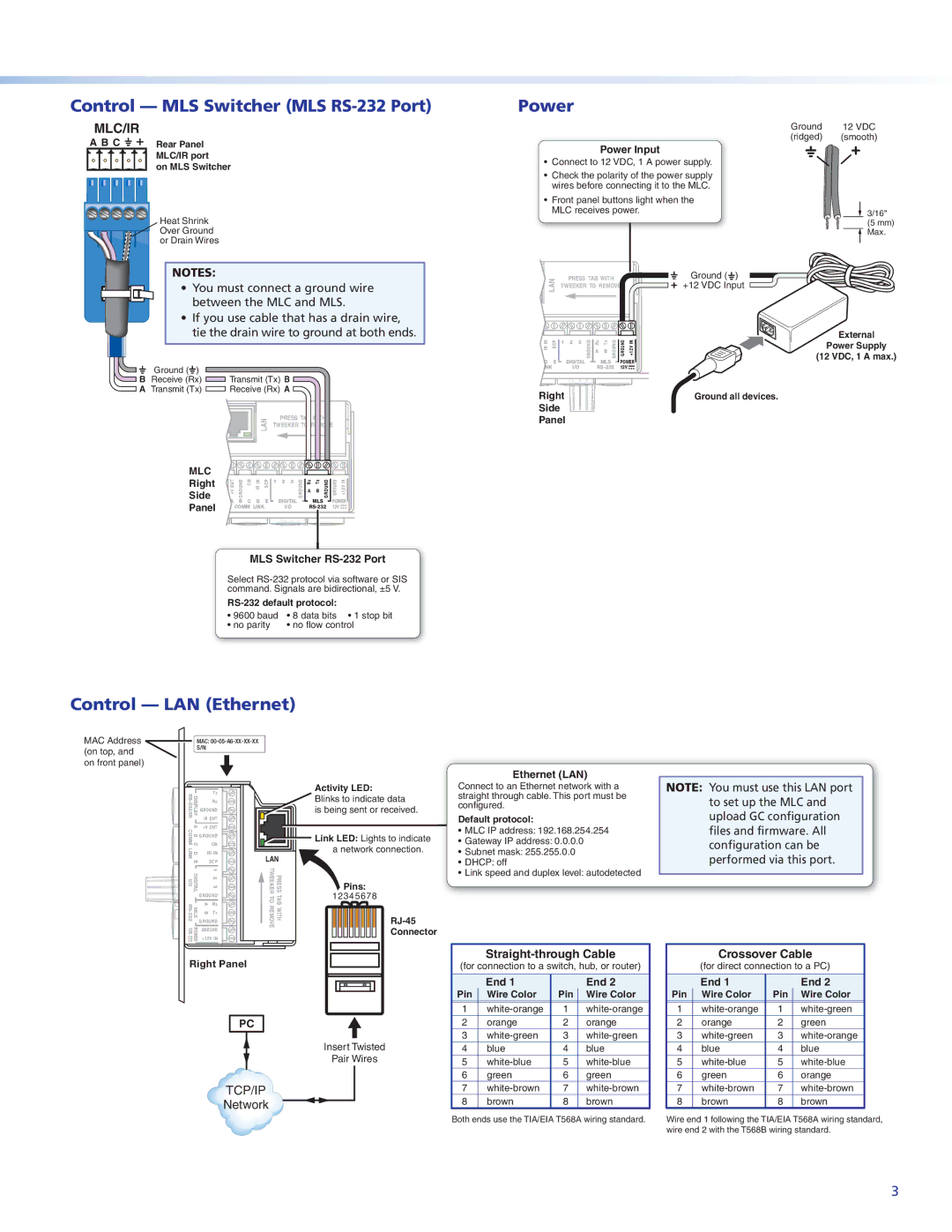
The architecture of the MLC 104 IP PLUS boasts advanced technology designed for seamless integration into existing AV systems. With its built-in IP control capability, the unit can communicate over Ethernet networks, providing flexibility and scalability for larger installations. The MLC 104 IP PLUS is compatible with Extron's extensive range of control products and can work in harmony with other devices, enhancing the overall system performance.
Security is also a paramount concern in modern networked environments, and the MLC 104 IP PLUS addresses this need with robust security features. It supports various authentication protocols to ensure that only authorized personnel can access and control AV resources. This focus on security helps to mitigate the risks associated with unauthorized access.
In terms of connectivity, the MLC 104 IP PLUS offers multiple ports that facilitate integration with a wide range of devices. With several HDMI inputs for video sources, as well as audio inputs and outputs, it is designed to handle high-definition content with ease. Additionally, the unit features a built-in microphone input, supporting audio reinforcement for presentations and discussions.
Another characteristic worth noting is the unit's support for Extron’s GlobalViewer Enterprise software. This software allows for centralized monitoring and management of AV systems across different locations, making it an ideal choice for organizations that require oversight over multiple environments.
With an emphasis on ease of use, reliability, and extensive functionality, the Extron MLC 104 IP PLUS stands out as a leading option for those seeking a sophisticated control solution for their audio-visual systems. Its combination of customizable features, secure access, and integration capabilities make it a vital tool for enhancing communication in educational, corporate, and collaborative settings.