MMX 32 VGA MTP • Setup Guide
|
| OUTPUT 1 |
|
|
| OUTPUT 2 |
| CONT | ||||
1 | 2 |
| 3 | 1 | 2 |
| 3 |
| ||||
|
|
|
|
|
|
|
|
|
|
|
|
|
|
|
|
|
|
|
|
|
|
|
|
|
|
|
|
|
|
|
|
|
|
|
|
|
|
|
|
|
|
|
|
|
|
| MMX 32 VGA MTP | |
INPUT 1 | INPUT 3 |
|
| OUTPUT 2 |
| 1 |
| REMOTE | |
AUDIO |
| AUDIO |
| PRE |
|
|
|
| |
|
|
| RGB/AUDIO | PEAK - | ISYNC - |
|
|
|
|
POWER |
|
| ON | TR | AUDIO | 1 | 2 3 | +5V | |
|
|
| |||||||
12V |
|
|
|
| L | R |
|
| ACT |
0.5A MAX |
|
|
|
|
|
| |||
|
|
|
|
|
|
| 2 |
|
|
AUDIO |
| AUDIO |
|
|
|
|
|
| Tx Rx |
INPUT 2 | OUTPUT 1 |
|
|
|
|
|
|
| |
|
|
|
|
|
|
|
| ||
This guide provides basic instructions for an experienced installer to set up and operate
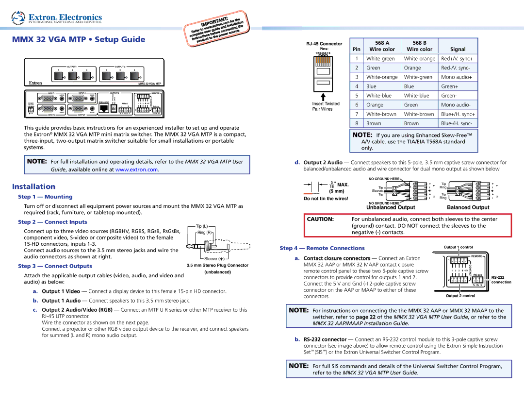
Pins:
12 3 4 5 6 78
Insert Twisted Pair Wires
| 568 A | 568 B |
|
Pin | Wire color | Wire color | Signal |
|
|
|
|
|
|
|
|
1 | Red+/V. sync+ | ||
|
|
|
|
2 | Green | Orange | |
|
|
|
|
3 | Mono audio+ | ||
|
|
|
|
4 | Blue | Blue | Green+ |
|
|
|
|
5 | Green- | ||
|
|
|
|
6 | Orange | Green | Mono audio- |
|
|
|
|
7 | Blue+/H. sync+ | ||
|
|
|
|
8 | Brown | Brown | |
|
|
|
|
the Extron® MMX 32 VGA MTP mini matrix switcher. The MMX 32 VGA MTP is a compact,
NOTE: For full installation and operating details, refer to the MMX 32 VGA MTP User Guide, available online at www.extron.com.
Installation
Step 1 — Mounting
Turn off or disconnect all equipment power sources and mount the MMX 32 VGA MTP as required (rack, furniture, or tabletop mounted).
NOTE: If you are using Enhanced
d.Output 2 Audio — Connect speakers to this
| NO GROUND HERE |
|
|
|
|
| L | Tip | L |
| Tip | Ring | ||
|
|
| ||
| Sleeves |
| Tip |
|
Do not tin the wires! | Tip | R | R | |
| Ring |
NO GROUND HERE | Balanced Output |
Unbalanced Output |
Step 2 — Connect Inputs
Connect up to three video sources (RGBHV, RGBS, RGsB, RsGsBs, component video,
Tip (L)
Ring (R)
CAUTION: For unbalanced audio, connect both sleeves to the center (ground) contact. DO NOT connect the sleeves to the negative
Connect audio sources to the 3.5 mm stereo jacks and wire the audio connectors as shown at right.
Step 3 — Connect Outputs
Attach the applicable output cables (video, audio, and video and audio) as below:
![]() Sleeve (
Sleeve (![]() )
)
3.5mm Stereo Plug Connector (unbalanced)
Step 4 — Remote Connections
a. Contact closure connectors — Connect an Extron |
MMX 32 AAP or MMX 32 MAAP contact closure |
remote control panel to these two |
connectors to provide control for outputs 1 and 2. |
Connect the 5 V and Gnd |
Output 1 control
REMOTE
1 |
1 | 2 | 3 | +5V | CONTACT | |
2 |
|
|
|
|
|
|
|
|
|
| Tx Rx |
![]() connection
connection
a. | Output 1 Video — Connect a display device to this female |
b. | Output 1 Audio — Connect speakers to this 3.5 mm stereo jack. |
connector on the AAP or MAAP to either of these |
connectors. |
Output 2 control
c. Output 2 Audio/Video (RGB) — Connect an MTP U R series or other MTP receiver to this |
Wire the connector as shown on the next page. |
Connect a projector or other RGB video output device to the receiver, and connect speakers |
for summed (L and R) mono audio output. |
NOTE: For instructions on connecting the the MMX 32 AAP or MMX 32 MAAP to the switcher, refer to page 22 of the MMX 32 VGA MTP User Guide, or refer to the MMX 32 AAP/MAAP Installation Guide.
b.
NOTE: For full SIS commands and details of the Universal Switcher Control Program, refer to the MMX 32 VGA MTP User Guide.