PA 250 specifications
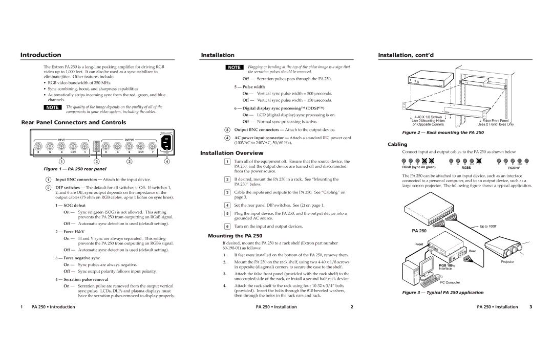
Extron Electronics PA 250 is a high-performance amplifier designed specifically for audio distribution in various environments, including conference rooms, classrooms, and auditoriums. This amplifier stands out due to its robust build, user-friendly design, and advanced features that cater to the needs of modern audio systems.One of the main features of the PA 250 is its powerful output capability. With a maximum output of 250 watts, it can easily drive multiple speakers simultaneously, making it suitable for larger venues. The amplifier operates in a Class D topology, which not only enhances efficiency but also reduces heat generation, ensuring reliable performance over extended periods.
The PA 250 is equipped with multiple input options, including balanced and unbalanced audio inputs. This versatility allows it to integrate seamlessly with various audio sources, such as microphones, mixers, and other audio equipment. The inclusion of a priority paging feature enhances its functionality, allowing critical announcements to take precedence over other audio sources, which is particularly beneficial in emergency situations.
Another important characteristic of the PA 250 is its built-in DSP (Digital Signal Processing). This technology enables users to fine-tune the audio output to suit specific environments by adjusting parameters such as equalization, compression, and limiting. The DSP provides users with greater control over the sound quality, ensuring clear and impactful audio reproduction, essential in professional settings.
In terms of connectivity, the PA 250 features both input and output connectors that support various cable types, making installation straightforward. The amplifier is also designed with reliability in mind, featuring overload protection to prevent damage during peak usage periods. Additionally, it includes a fan-less design for quiet operation, ensuring that noise from the amplifier does not interfere with presentations or speeches.
For ease of use, the PA 250 is equipped with a front panel that includes controls for volume adjustment, input selection, and indicator lights for monitoring performance. This user-friendly interface allows for quick adjustments during events or presentations.
Overall, the Extron PA 250 amplifier exemplifies the integration of advanced technology and practical features designed to meet the demands of modern audio environments. Whether for educational institutions, enterprise settings, or public venues, the PA 250 delivers reliability, versatility, and exceptional audio quality, making it a valuable addition to any audio system.

