Installation and Operation, cont’d
Front Panel Features
GAIN PEAKING
LF HF
PA 300
PEAKING AMPLIFIER
1 2 3
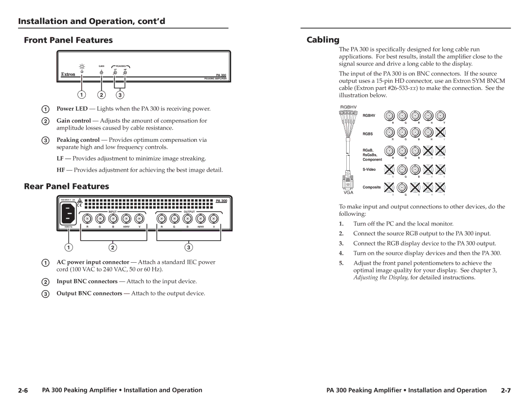
a Power LED — Lights when the PA 300 is receiving power.
b Gain control — Adjusts the amount of compensation for amplitude losses caused by cable resistance.
c Peaking control — Provides optimum compensation via separate high and low frequency controls.
LF — Provides adjustment to minimize image streaking.
HF — Provides adjustment for achieving the best image detail.
Cabling
The PA 300 is specifically designed for long cable run applications. For best results, install the amplifier close to the signal source and drive a long cable to the display.
The input of the PA 300 is on BNC connectors. If the source output uses a
RGBHV
RGBHV
R G B H V
RGBS
R G B H V
RGsB,
RsGsBs,
Component | R | G | B | H | V |
|
|
|
|
| |
|
|
|
|
| |
| R | G | B | H | V |
Rear Panel Features
![]() .3A
.3A
INPUT
50/60 Hz | R | G | B | H/HV | V | |
|
|
|
|
|
|
|
|
|
|
|
|
|
|
PA 300
OUTPUT
R | G | B | H/HV | V |
Composite |
|
|
|
|
VGA | G | B | H | V |
R |
To make input and output connections to other devices, do the following:
1. | Turn off the PC and the local monitor. |
2. | Connect the source RGB output to the PA 300 input. |
3. | Connect the RGB display device to the PA 300 output. |
123
a AC power input connector — Attach a standard IEC power cord (100 VAC to 240 VAC, 50 or 60 Hz).
b Input BNC connectors — Attach to the input device. c Output BNC connectors — Attach to the output device.
4. | Turn on the source display devices and then the PA 300. |
5. | Adjust the front panel potentiometers to achieve the |
| optimal image quality for your display. See chapter 3, |
| Adjusting the Display, for detailed instructions. |
PA 300 Peaking Amplifier • Installation and Operation | PA 300 Peaking Amplifier • Installation and Operation |
