SW4 3G HD-SDI Setup Guide
AUTO |
|
|
SWITCH | 1 | 2 |
|
ACTIVE
MODE NORMAL
3
AUTO
RATE
NOT
![]() RECOGNIZED
RECOGNIZED
4 | 2.97 Gbps |
![]() 1.485 Gbps
1.485 Gbps
![]() 270 Mbps
270 Mbps
SW4 3G
1 | 2 INPUTS 3 | 4 | 1OUTPUTS2 |
Tx Rx ![]()
50/60 Hz
The Extron® SW4 3G
This guide provides basic instructions for an experienced installer to set up and operate this switcher.
Installation
1.Turn off all of the equipment and disconnect it from the power source.
2.(Optional) If desired, mount the switcher on a 6 inch or 9.5 inch deep rack shelf.
3.Connect up to four SDI,
![]() NOTE: Each input is equalized regardless of the rate.
NOTE: Each input is equalized regardless of the rate.
Switcher | Computer | |
5 | 1 | |
4.Connect one or two video SDI,
![]() NOTE: Outputs 1 and 2 output identical signals.
NOTE: Outputs 1 and 2 output identical signals.
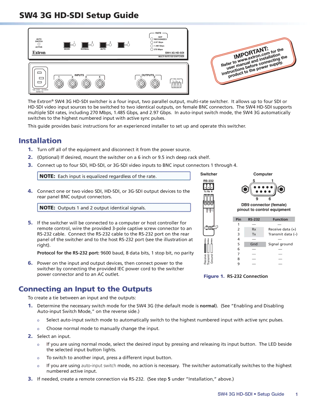
5.If the switcher will be connected to a computer or host controller for remote control, wire the provided
Protocol for the
6.Power on the input and output devices, then connect power to the switcher by connecting the provided IEC power cord to the switcher power connector and to an AC outlet.
Tx Rx ![]()
|
| 9 | 6 |
|
| DB9 connector (female) | |
| pinout to control equipment | ||
| Pin | Function | |
| 1 | — | — |
| 2 | Rx | Receive data (+) |
| 3 | Tx | Transmit data |
| 4 | — | — |
| 5 | Gnd | Signal ground |
| 6 | — | — |
Receive Transmit Ground | 7 | — | — |
9 | — | — | |
| 8 | — | — |
Figure 1. RS-232 Connection
Connecting an Input to the Outputs
To create a tie between an input and the outputs:
1.Determine the necessary switch mode for the SW4 3G (the default mode is normal). (See “Enabling and Disabling
оо Select
2.Select an input.
оо If you are using normal mode, select the desired input by pressing and releasing its input button. The LED beside the selected input button lights.
оо To switch to another input, press a different input button.
оо If you are using
3.If needed, create a remote connection via
SW4 3G | 1 |