Equipment Parts
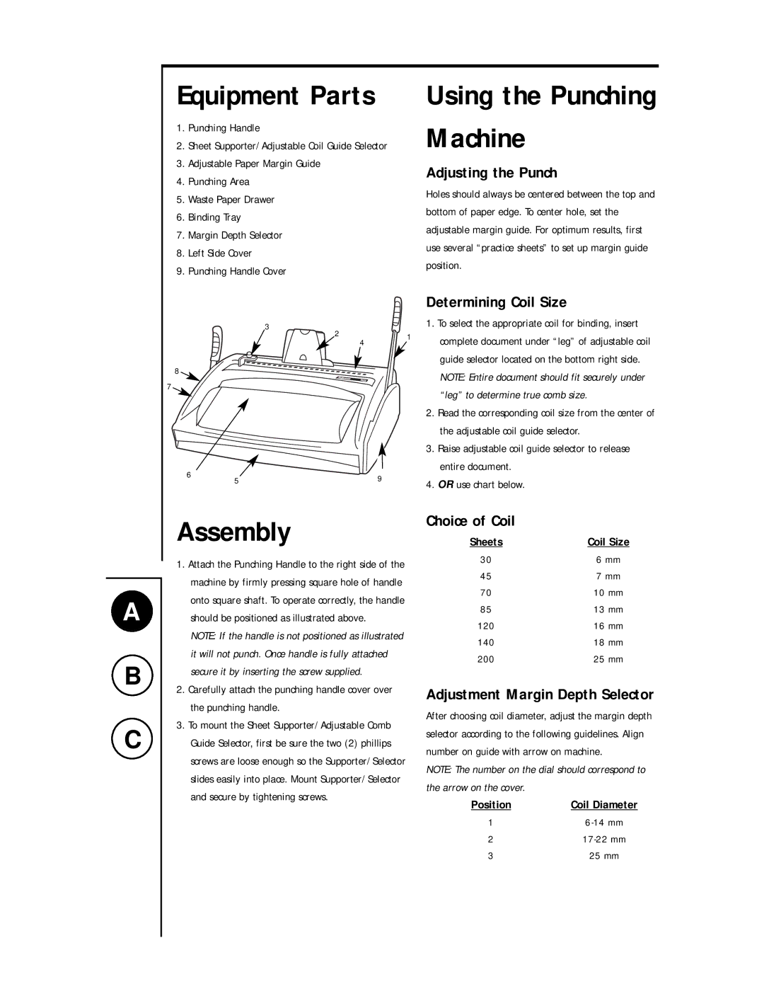
1.Punching Handle
2.Sheet Supporter/Adjustable Coil Guide Selector
3.Adjustable Paper Margin Guide
4.Punching Area
5.Waste Paper Drawer
6.Binding Tray
7.Margin Depth Selector
8.Left Side Cover
9.Punching Handle Cover
Using the Punching Machine
Adjusting the Punch
Holes should always be centered between the top and bottom of paper edge. To center hole, set the adjustable margin guide. For optimum results, first use several “practice sheets” to set up margin guide position.
|
|
|
| Determining Coil Size |
| 3 | 2 | 1 | 1. To select the appropriate coil for binding, insert |
|
| complete document under “leg” of adjustable coil | ||
|
| 4 | ||
8 |
|
|
| guide selector located on the bottom right side. |
|
|
| NOTE: Entire document should fit securely under | |
7 |
|
|
| |
|
|
| “leg” to determine true comb size. | |
|
|
|
| |
|
|
|
| 2. Read the corresponding coil size from the center of |
|
|
|
| the adjustable coil guide selector. |
|
|
|
| 3. Raise adjustable coil guide selector to release |
6 | 5 |
| 9 | entire document. |
| 4. OR use chart below. | |||
|
| |||
|
|
|
A
B
C
Assembly
1.Attach the Punching Handle to the right side of the machine by firmly pressing square hole of handle onto square shaft. To operate correctly, the handle should be positioned as illustrated above.
NOTE: If the handle is not positioned as illustrated it will not punch. Once handle is fully attached secure it by inserting the screw supplied.
2.Carefully attach the punching handle cover over the punching handle.
3.To mount the Sheet Supporter/Adjustable Comb Guide Selector, first be sure the two (2) phillips screws are loose enough so the Supporter/Selector slides easily into place. Mount Supporter/Selector and secure by tightening screws.
Choice of Coil
Sheets | Coil Size |
30 | 6 mm |
45 | 7 mm |
70 | 10 mm |
85 | 13 mm |
120 | 16 mm |
140 | 18 mm |
200 | 25 mm |
Adjustment Margin Depth Selector
After choosing coil diameter, adjust the margin depth selector according to the following guidelines. Align number on guide with arrow on machine.
NOTE: The number on the dial should correspond to the arrow on the cover.
Position
1
2
3