A
B
C
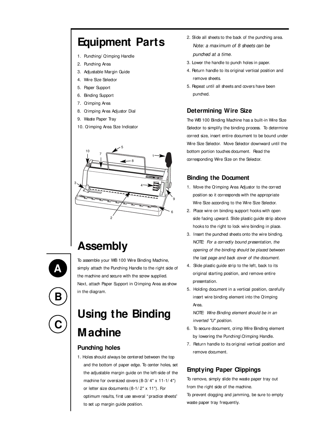
Equipment Parts
1.Punching/Crimping Handle
2.Punching Area
3.Adjustable Margin Guide
4.Wire Size Selector
5.Paper Support
6.Binding Support
7.Crimping Area
8.Crimping Area Adjustor Dial
9.Waste Paper Tray
10.Crimping Area Size Indicator
10 |
| 5 | |
7 | 1 | ||
| |||
|
| ||
|
| 8 |
3 | 4 |
|
9
![]() 6
6
2
Assembly
To assemble your WB 100 Wire Binding Machine, simply attach the Punching Handle to the right side of the machine and secure with the screw supplied. Next, attach Paper Support in Crimping Area as show in the diagram.
Using the Binding Machine
Punching holes
1.Holes should always be centered between the top and the bottom of paper edge. To center holes, set the adjustable margin guide on the
2. Slide all sheets to the back of the punching area.
Note: a maximum of 8 sheets can be punched at a time.
3.Lower the handle to punch holes in paper.
4.Return handle to its original vertical position and remove sheets.
5.Repeat until all sheets and covers have been punched.
Determining Wire Size
The WB 100 Binding Machine has a
Binding the Document
1.Move the Crimping Area Adjustor to the correct position so it corresponds with the appropriate Wire Size according to the Wire Size Selector.
2.Place wire on binding support hooks with open side facing upward. Slide plastic guide strip above hooks to the right to lock wire binding in place.
3.Insert the punched sheets onto the wire binding. NOTE: For a correctly bound presentation, the opening of the binding should be placed between the last page and back cover of the document.
4.Slide plastic guide strip to the left, back to its original starting position, and remove entire presentation.
5.Holding document in a vertical position, carefully insert wire binding element into the Crimping Area.
NOTE: Wire Binding element should be in an inverted "U" position.
6.To secure document, crimp Wire Binding element by lowering the Punching\Crimping Handle.
7.Return handle to its original vertical position and remove document.
Emptying Paper Clippings
To remove, simply slide the waste paper tray out from the right side of the machine.
To prevent clogging and jamming, be sure to empty waste paper tray frequently.