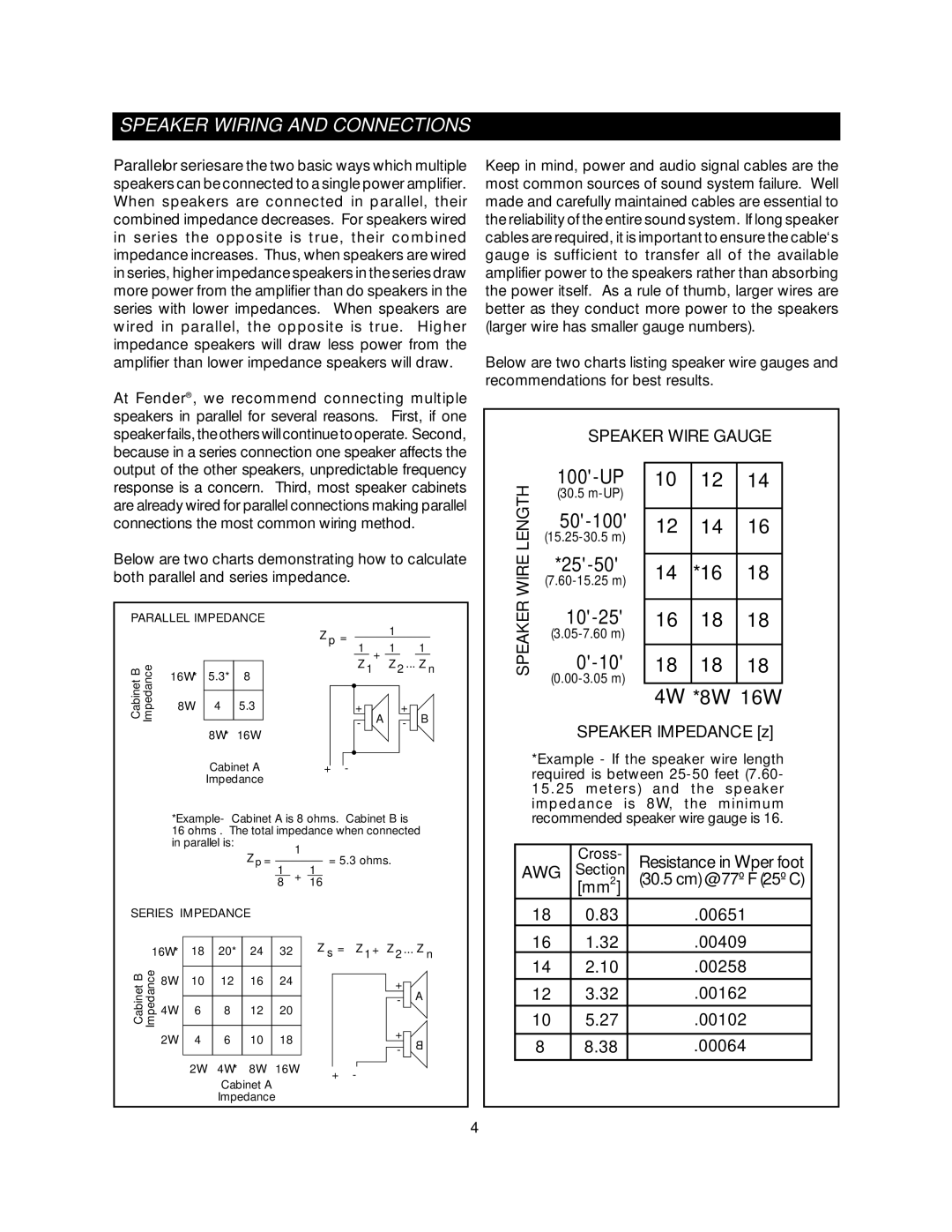
1201X, 1205X, 1110X specifications
Fender has long been a revered name in the world of guitars, and the Fender 1110X, 1201X, and 1205X models showcase the brand's dedication to craftsmanship and innovation. Each of these models carries its own unique set of features and technologies that cater to both seasoned musicians and beginners alike.Starting with the Fender 1110X, this guitar is designed for versatility and playability. It boasts a solid spruce top that delivers a bright and resonant tone, while its mahogany back and sides provide warmth and depth. One standout feature of the 1110X is its comfortable neck profile, allowing for easier chord transitions and soloing. The incorporation of a Fishman Presys electronics system enables players to amplify their sound with natural clarity, making it an excellent choice for both studio recording and live performances.
Moving on to the Fender 1201X, this model stands out for its rich tonal possibilities. It features a solid Sitka spruce top combined with rosewood back and sides, resulting in a balanced sound with a pleasing low end. The 1201X also includes an innovative scalloped bracing pattern that enhances the guitar's responsiveness and projection. Additionally, this model is equipped with advanced electronics, including the Fishman Sonitone system, which offers easy-to-use controls for shaping the amplified tone. Its elegant aesthetics, complete with a glossy finish and intricate inlays, also make it visually captivating.
Finally, the Fender 1205X elevates the series with its premium craftsmanship and superior sound quality. This model is built with a solid Sitka spruce top, paired with exceptional Indian rosewood for the back and sides, creating an exquisite resonance and sustain. The 1205X features hand-scalloped bracing that not only amplifies tonal warmth but also adds to the guitar's overall dynamic range. The inclusion of the Fishman Matrix VT Enhance electronics allows for seamless plug-and-play performance, ensuring that the guitar's acoustic qualities are preserved when amplified. Players will also appreciate the stunning visual details, such as the mother-of-pearl inlays and binding.
In summary, the Fender 1110X, 1201X, and 1205X models all represent a commitment to quality, sound, and playability. Each guitar is imbued with unique features and technologies that enable players to express their musicality, whether they are jamming at home or performing on stage. These models exemplify the spirit of Fender, merging tradition with modern innovation to cater to a wide range of playing styles and preferences.

