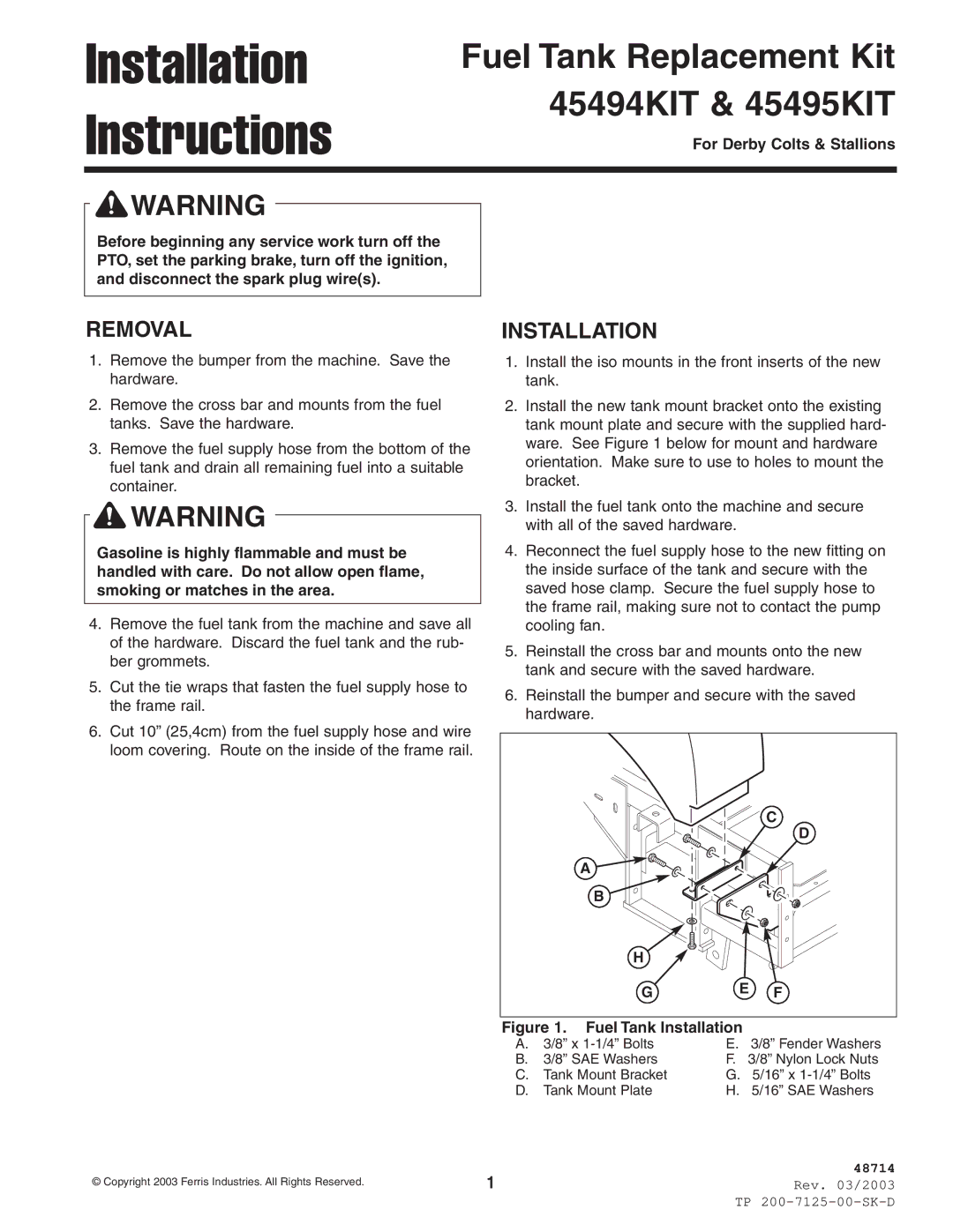
45494KIT, 45495KIT specifications
Ferris Industries has long been a prominent name in the lawn care and outdoor equipment industry, and their 45495KIT and 45494KIT product offerings illustrate the company’s commitment to innovation and quality. These two kits are designed specifically for users who value efficiency, superior performance, and ease of use, making them a top choice for both professional landscapers and dedicated homeowners alike.The Ferris 45495KIT is engineered for robust performance, featuring a powerful engine that ensures reliable operation even under the most demanding conditions. This kit is equipped with advanced technologies such as Hydro-Gear® drive systems that provide enhanced torque and precise maneuverability, allowing operators to handle various terrains with ease. Additionally, the 45495KIT includes an innovative suspension system that significantly improves comfort during extended use, reducing operator fatigue and increasing productivity.
Meanwhile, the Ferris 45494KIT offers similar quality but is designed with slightly different specifications to cater to various user needs. This kit focuses on versatility, boasting a variety of compatible attachments that enable users to customize their equipment for specific tasks. The 45494KIT features a state-of-the-art cutting deck design, which promotes a superior cut while enhancing grass discharge and reducing clumping.
Both kits are constructed with durable materials, ensuring longevity and reliability in all weather conditions. The decks are built with high-strength steel, complemented by rust-resistant coatings to prolong the lifespan of the equipment. Safety features such as automatic blade shutoff and durable, easy-grip controls make operation intuitive and secure.
Moreover, both models emphasize maintenance ease, with access points strategically placed for quick oil changes and routine checks. This attention to user-friendly design extends to the ergonomic controls and adjustable features that allow operators to tailor the equipment to their personal preferences.
In conclusion, Ferris Industries’ 45495KIT and 45494KIT highlight the brand’s dedication to quality craftsmanship, technological advancement, and user-centric design. Whether chosen for professional landscaping or personal use, these kits represent a compelling option for anyone in need of reliable, efficient equipment for lawn care. The combination of advanced features, durable construction, and thoughtful design positions these kits as prime choices in the competitive market of outdoor power equipment.

