HUMIDIFIERS | |
SUPPLEMENT TO THE ELECTRONIC STEAM POWER HUMIDIFIERS | |
| MODEL # S2000 AND S2020 |
REPAIRS SHOULD BE PERFORMED BY A QUALIFIED TECHNICIAN
To replace the Thermistor Probe in the “S” series steam
humidifier, you must unplug and shut down your steam
humidifier and allow it to cool. The water tank must be drained, the water supply, drain lines and electrical wiring must be disconnected and the unit removed from the duct. Pull straight up on the Green terminal block to disconnect it from the unit.
Place the unit on a flat working surface.
Using a phillips screwdriver, remove the two screws that hold the baffle plate to the tank. Lift the baffle slightly back to clear the water level probe and then straight up and out of the tank.
Unplug the automatic drain valve assembly from the side of the front cover. Snip the plastic wire tie that secures the drain valve wires to the main power cord. Now use an adjustable wrench at the brass “T” adapter to unscrew the entire drain valve assembly. DO NOT use the drain valve itself as leverage when removing or
Now use a phillips screwdriver and loosen the four screws securing the front cover and remove the front cover.
Use a 5/16” nut driver to loosen and remove the hex nut which secures the water level probe to the printed circuit board. Remove the ground screw at the upper right hand corner of the printed circuit board. Remove the two small phillips screws at the bottom corners of the printed circuit board. The printed circuit board can now be laid flat and out of the way. Be careful not to damage it! Locate the wires from the Thermistor Probe and trace them to where they connect to the printed circuit board. Pull the connector off of the board.
Use two 7/16” combination wrenches, one as a backup on the thermistor probe side, and the other wrench on the hex nut. Loosen the hex nut on the Thermistor Probe assembly. It will be a little tight due to the Loctite on the threads from the factory. Loosen the nut all the way. Now cut both wire leads in order to remove the nut and pull the thermistor probe out of the tank. Discard the old Thermistor Probe and the cut wire/connector.
Now remove the new Thermistor Probe and the other accessories from the bag. Put the ”O” ring onto the threads of the thermistor probe and all the way up to the base of the Thermistor Probe. Feed the thermistor probe’s wire leads through the hole in the tank and out the front. Position the thermistor probe into the hole. Now feed one wire at a time through the hex nut and thread the hex nut onto the Thermistor Probe. Tighten the hex nut firmly.
Do not over tighten and damage the “O” ring.
Now insert each wire into the molded plastic connector until it snaps in to place. Plug the connector back on to the printed circuit board J2 pins.
Position the printed circuit board into place and secure with the two small phillips screws at each bottom corner.
Make sure that no wires are pinched between the transformer and the front plate. Adjust the wires as necessary.
NOTE: Loose spade connectors can overheat and damage the wires. Use pliers to
Doing so will void your warranty.
Tighten the ground screw at the upper right hand corner. Position the water level probe back into the hole on the printed circuit board.
Now you can
Apply Teflon tape to the threads of the “T” adapter on the automatic drain valve. Screw the entire drain valve assembly back onto the drain fitting and tighten with an adjustable wrench. DO NOT use the solenoid valve itself as leverage to turn and tighten the assembly. Doing so will damage the valve. Tighten and position the drain assembly to the original position. Plug the drain valve molded connector back in on the side of the front cover until it snaps into place. Secure the drain valve wires with the short cable tie.
Review the entire project to be sure that nothing has been overlooked.
Now insert the unit back into the duct and secure it.
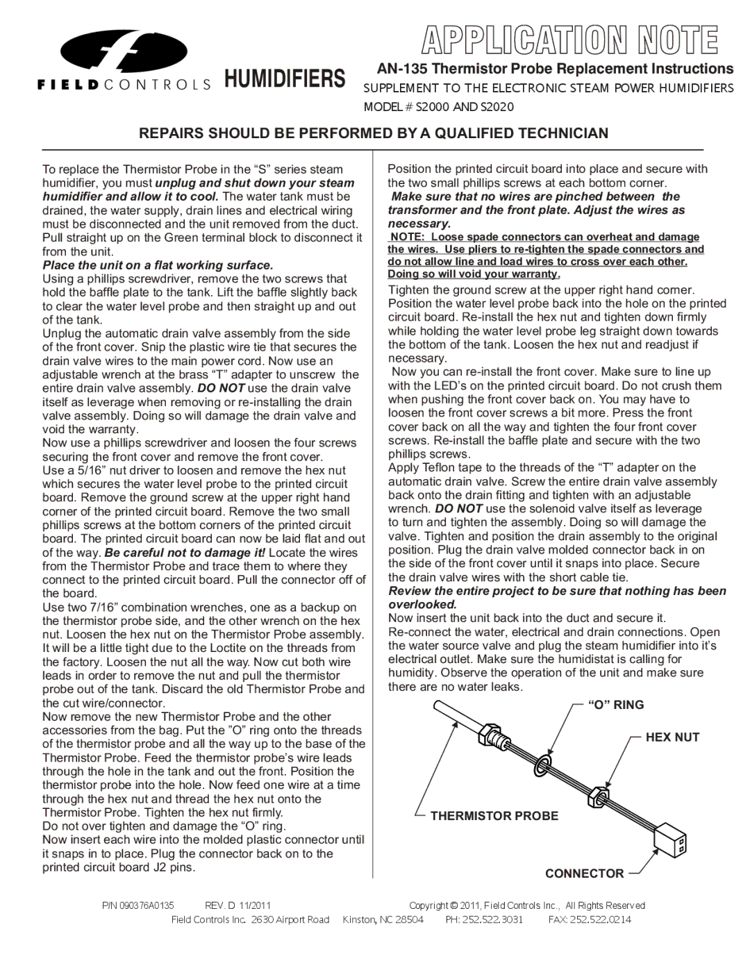
“O” RING
HEX NUT
THERMISTOR PROBE
CONNECTOR
P/N 090376A0135 REV. C Copyright © | ||
P/N 090376A0135 | REV. D 11/2011 | Copyright © 2011, Field Controls Inc., All Rights Reserved |
EWC Controls Inc. Field385ControlsHighwayInc33. ![]() 2630Englishtown,Airport RoadNJ
2630Englishtown,Airport RoadNJ ![]()