initial setup
camera and power connections
step 1 ... Installing cameras 
Mounting Cameras and Running Cable
Select the position for the camera and secure the camera stand. Screw the camera onto the stand. Adjust camera to the proper view angle. Make sure the lens is upright relative to the subject. Tighten the thumb bolt. First Alert cameras can be either ceiling or wall mounted by simply reversing the camera stand mounting. See “Camera Orientation” Info box. Holes are provided on both the bottom and back of the camera housing to accommodate most mounting requirements. Run cable from camera to DVR location. See Information box below on “Longer Cable Runs”.
Camera Orientation
It’s important the camera is mounted correctly to ensure the image is not upside down as the cam- era lens can only be positioned one way.
|
|
| Longer Cable Runs |
|
|
| Longer cable runs may require an upgrade to |
|
|
| RG59 Coax cable. First Alert kits ship with eco- |
Camera - Wall Mounted |
|
| nomical AV cable that is designed to work well up |
|
| to the length of cable provided, usually around | |
|
|
| |
|
|
| 60 feet. If longer distances between camera and |
|
|
| DVR are required, you will need to upgrade to RG59 Coax cable. We |
|
|
| provide several lengths up to 300 feet. In addition, if you need to run |
| Camera - Ceiling | Mounted | cable for |
|
initial setup
system operation
Step 3 ... system start up
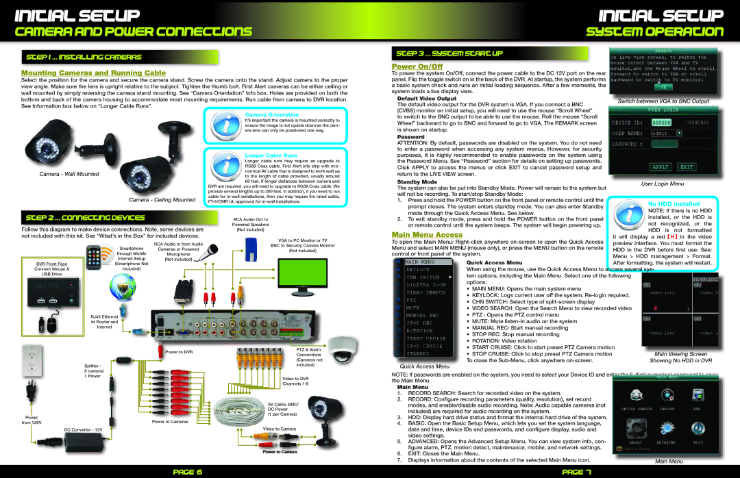
Power On/Off
To power the system On/Off, connect the power cable to the DC 12V port on the rear panel. Flip the toggle switch on in the back of the DVR. At startup, the system performs a basic system check and runs an initial loading sequence. After a few moments, the system loads a live display view.
Default Video Output | Switch between VGA to BNC Output | |
The default video output for the DVR system is VGA. If you connect a BNC | ||
| ||
(CVBS) monitor on initial setup, you will need to use the mouse “Scroll Wheel” |
| |
to switch to the BNC output to be able to use the mouse. Roll the mouse “Scroll |
| |
Wheel” backward to go to BNC and forward to go to VGA. The REMARK screen |
| |
is shown on startup. |
| |
Password |
| |
ATTENTION: By default, passwords are disabled on the system. You do not need |
| |
to enter a password when accessing any system menus. However, for security |
| |
purposes, it is highly recommended to enable passwords on the system using |
| |
the Password Menu. See “Password” section for details on setting up passwords. |
| |
Click APPLY to access the menus or click EXIT to cancel password setup and |
| |
return to the LIVE VIEW screen. |
| |
Standby Mode |
| |
User Login Menu | ||
The system can also be put into Standby Mode. Power will remain to the system but | ||
| ||
will not be recording. To start/stop Standby Mode: |
| |
1. Press and hold the POWER button on the front panel or remote control until the | No HDD installed | |
prompt closes. The system enters standby mode. You can also enter Standby | ||
NOTE: If there is no HDD |
Step 2 ... connecting devices
Follow this diagram to make device connections. Note, some devices are not included with this kit. See “What’s in the Box” for included devices.
RCA Audio Out to Powered Speakers (Not included)
mode through the Quick Access Menu. See below. | installed, or the | HDD is | ||
2. To exit standby mode, press and hold the POWER button on the front panel | ||||
not | recognized, | or the | ||
or remote control until the system beeps. The system will begin powering up. | ||||
Main Menu Access | HDD | is not formatted | ||
it will display a red【H】in the video | ||||
DVR Front Face
Connect Mouse &
USB Drive
Smartphone
through Mobile
Internet Setup
![]()
![]()
![]()
![]() (Smartphone Not
(Smartphone Not
included)
RJ45 Ethernet
to Router and
Internet
Splitter -
8 camera/
1 Power
RCA Audio In from Audio
Cameras or Powered
Microphone
(Not included)
Power to DVR
VGA to PC Monitor or TV
BNC to Security Camera Monitor
(Not included)
PTZ & Alarm Connections (Cameras not included)
Video to DVR
Channels
AV Cable: BNC/
DC Power
To open the Main Menu: | preview interface. You must format the | |
Menu and select MAIN MENU (mouse only), or press the MENU button on the remote | HDD in the DVR before first use. See: | |
control or front panel of the system. | ||
Menu > HDD management > Format. | ||
| ||
Quick Access Menu | After formatting, the system will restart. | |
When using the mouse, use the Quick Access Menu to access several sys- | ||
tem options, including the Main Menu. Select one of the following options:
•MAIN MENU: Opens the main system menu
•KEYLOCK: Logs current user off the system.
•CHN SWITCH: Select type of
•VIDEO SEARCH: Open the Search Menu to view recorded video
•PTZ : Opens the PTZ control menu
•MUTE: Mute
•MANUAL REC: Start manual recording
•STOP REC: Stop manual recording
•ROTATION: Video rotation
•START CRUISE: Click to start preset PTZ Camera motion
• STOP CRUISE: Click to stop preset PTZ Camera motion | Main Viewing Screen |
To close the | Showing No HDD in DVR |
Quick Access Menu
NOTE: If passwords are enabled on the system, you need to select your Device ID and enter the
Main Menu | |
1. | RECORD SEARCH: Search for recorded video on the system. |
2. | RECORD: Configure recording parameters (quality, resolution), set record |
| modes, and enable/disable audio recording. Note: Audio capable cameras (not |
| included) are required for audio recording on the system. |
|
|
|
| ||
Power |
|
| Power to Cameras | ||
from 120V |
|
| |||
|
|
| DC Converter - 12V |
|
|
|
|
|
| ||
|
|
|
|
|
|
|
|
|
|
|
|
(1 per Camera)
Video to Camera
3. | HDD: Display hard drive status and format the internal hard drive of the system. |
4. | BASIC: Open the Basic Setup Menu, which lets you set the system language, |
| date and time, device IDs and passwords, and configure display, audio and |
| video settings. |
5. | ADVANCED: Opens the Advanced Setup Menu. You can view system info, con- |
| figure alarm, PTZ, motion detect, maintenance, mobile, and network settings. |
Powerr tto Camerra
6. | EXIT: Closes the Main Menu. |
|
7. | Displays information about the contents of the selected Main Menu icon. | Main Menu |
Page 6 | Page 7 |
|
|